MCR12N Ver la hoja de datos (PDF) - ON Semiconductor
Número de pieza
componentes Descripción
Fabricante
MCR12N Datasheet PDF : 4 Pages
| |||
MCR12D, MCR12M, MCR12N
THERMAL CHARACTERISTICS
Characteristic
Thermal Resistance,
Junction−to−Case
Junction−to−Ambient
Maximum Lead Temperature for Soldering Purposes 1/8″ from Case for 10 Seconds
ELECTRICAL CHARACTERISTICS (TJ = 25°C unless otherwise noted)
Characteristic
OFF CHARACTERISTICS
Peak Repetitive Forward or Reverse Blocking Current
(VD = Rated VDRM and VRRM; Gate Open)
ON CHARACTERISTICS
TJ = 25°C
TJ = 125°C
Peak Forward On−State Voltage (Note 2) (ITM = 24 A)
Gate Trigger Current (Continuous dc) (VD = 12 V; RL = 100 W)
Holding Current (VD = 12 V, Gate Open, Initiating Current = 200 mA)
Latch Current (VD = 12 V, IG = 20 mA)
Gate Trigger Voltage (Continuous dc) (VD = 12 V; RL =100 W)
DYNAMIC CHARACTERISTICS
Critical Rate of Rise of Off−State Voltage
(VD = Rated VDRM, Exponential Waveform, Gate Open, TJ = 125°C)
Repetitive Critical Rate of Rise of On−State Current
IPK = 50 A, Pw = 40 msec, diG/dt = 1 A/msec, Igt = 50 mA
2. Indicates Pulse Test: Pulse Width v 2.0 ms, Duty Cycle v 2%.
Symbol
RqJC
RqJA
TL
Value
2.2
62.5
260
Unit
°C/W
°C
Symbol Min Typ Max Unit
IDRM,
IRRM
mA
−
− 0.01
−
−
2.0
VTM
IGT
IH
IL
VGT
dv/dt
di/dt
−
−
2.2
V
2.0 8.0 20
mA
4.0 20
40
mA
6.0 25
60
mA
0.5 0.65 1.0
V
100 250
−
V/ms
−
−
50 A/ms
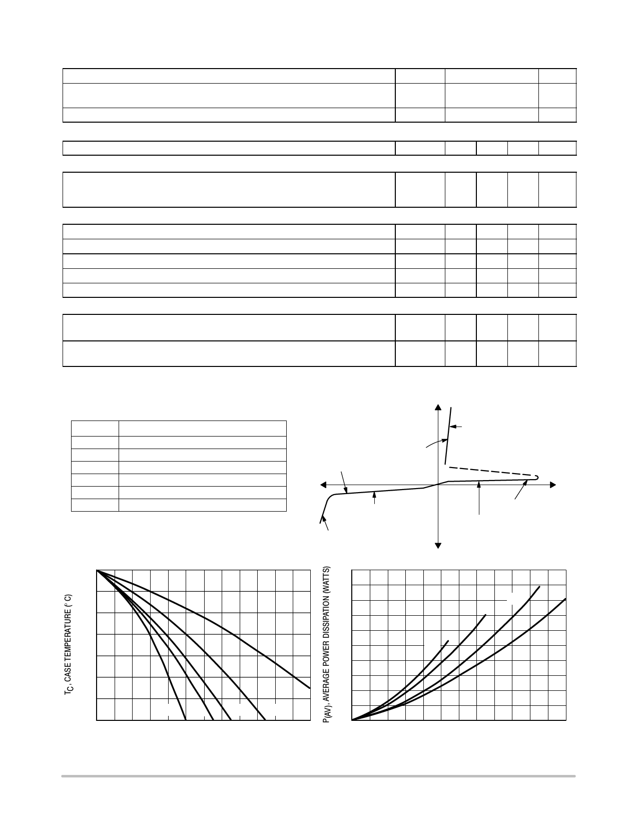
Voltage Current Characteristic of SCR + Current
Anode +
Symbol
VDRM
IDRM
VRRM
IRRM
VTM
IH
Parameter
Peak Repetitive Off State Forward Voltage
Peak Forward Blocking Current
Peak Repetitive Off State Reverse Voltage
Peak Reverse Blocking Current
Peak On State Voltage
Holding Current
IRRM at VRRM
on state
VTM
IH
Reverse Blocking Region
(off state)
Reverse Avalanche Region
Anode −
+ Voltage
IDRM at VDRM
Forward Blocking Region
(off state)
125
120
115
110
105
dc
100
95
90
012
30° 60°
3 45 6
90°
78
180°
9 10 11 12
IT(RMS), RMS ON−STATE CURRENT (AMPS)
Figure 1. Typical RMS Current Derating
20
18
16
14
12
10
8
6
4
2
0
0
90°
30°
180°
dc
1 2 3 4 5 6 7 8 9 10 11 12
IT(AV), AVERAGE ON−STATE CURRENT (AMPS)
Figure 2. On−State Power Dissipation
http://onsemi.com
2
Share Link: 