NCP1232DR2 Ver la hoja de datos (PDF) - ON Semiconductor
Número de pieza
componentes Descripción
Fabricante
NCP1232DR2 Datasheet PDF : 8 Pages
| |||
NCP1232
Power Monitor
The NCP1232 detects out-of-tolerance power supply
conditions and warns a processor-based system of an
impending power failure. When VCC is detected as below
the preset level defined by TOL, the VCC comparator
outputs the signals RST and RST. If TOL is connected to
ground, the RST and RST signals become active as VCC falls
below 4.75 volts. If TOL is connected to VCC, the RST and
RST become active as VCC falls below 4.5 volts. Because
the processing is stopped at the last possible moment of valid
VCC, the RST and RST are excellent control signals for a mP.
The reset outputs will remain in their active states until VCC
has been continuously in-tolerance for a minimum of 250
msec allowing the power supply and mP to stabilize before
RST is released.
Push-button Reset Input
The debounced manual reset input (PB RST) manually
forces the reset outputs into their active states. Once PB RST
has been low for a time, tPBD, the push-button delay time,
the reset outputs go active. The reset outputs remain in their
active states for a minimum of 250 msec after PB RST rises
above VIH (Figure 3).
A mechanical push-button or active logic signal can drive
the PB RST input. The debounced input ignores input pulses
less than 1 msec and is guaranteed to recognize pulses of
20 msec or greater. No external pull-up resistor is required
because the PB RST input has an internal pull-up to VCC of
approximately 100 mA.
Watchdog Timer
When the ST input is not stimulated for a preset time
period, the watchdog timer function forces RST and RST
signals to the active state. The preset time period is
determined by the TD inputs to be 150 msec with TD
connected to ground, 600 msec with TD open, or 1200 msec
with TD connected to VCC, typical. The watchdog timer
starts timing out from the set time period as soon as RST and
RST are inactive. If a high-to-low transition occurs on the
ST input pin prior to time-out, the watchdog timer is reset
and begins to time-out again. If the watchdog timer is
allowed to time-out, then the RST and RST signals are
driven to the active state for 250 msec minimum (Figure 2).
The software routine that strobes ST is critical. The code
must be in a section of software that is executed regularly so
the time between toggles is less than the watchdog time-out
period. One common technique controls the mP I/O line from
two sections of the program. The software might set the I/O
line high while operating in the foreground mode and set it
low while in the background or interrupt mode. If both
modes do not execute correctly, the watchdog timer issues
reset pulses.
Supply Monitor Noise Sensitivity
The NCP1232 is optimized for fast response to
negative-going changes in VDD. Systems with an inordinate
amount of electrical noise on VDD (such as systems using
relays), may require a 0.01 mF or 0.1 mF bypass capacitor to
reduce detection sensitivity. This capacitor should be
installed as close to the NCP1232 as possible to keep the
capacitor lead length short.
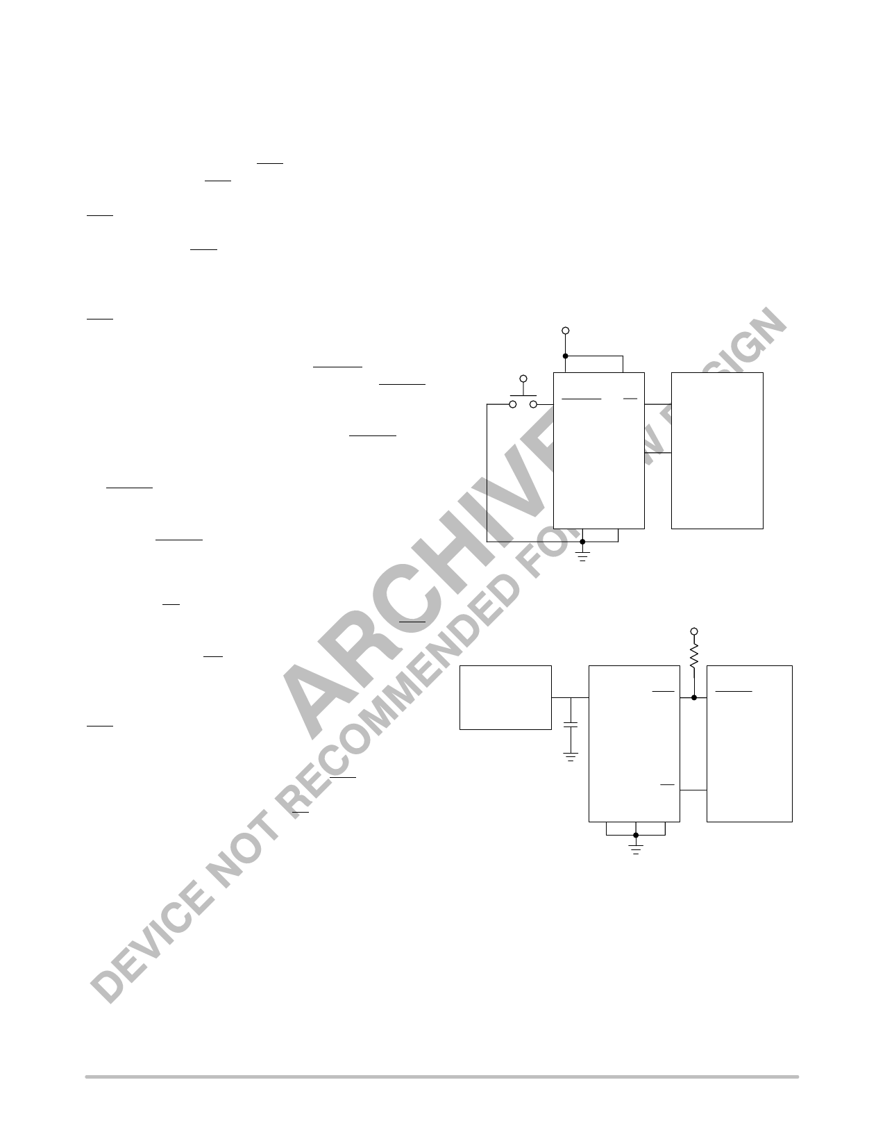
+5 V
VCC
TD
PB RST ST
RST
NCP1232
GND TOL
I/O
MICRO-
PROCESSOR
RESET
Figure 1. Push-button Reset
+5 V
10 KW
3-TERMINAL
+5 V
VCC
REGULATOR
RST
0.1 mF
NCP1232
RESET
MICRO-
PROCESSOR
ST
I/O
TD TOL GND
Figure 2. Watchdog Timer
http://onsemi.com
5
Share Link: 