TS19376 Ver la hoja de datos (PDF) - TSC Corporation
Número de pieza
componentes Descripción
Fabricante
TS19376 Datasheet PDF : 8 Pages
| |||
TS19376
1A Step-down High Brightness LED Driver
Application Information
Operation Description
The device, in conjunction with the coil (L1) and current sense resistor (RS), forms a self oscillating continuous-
mode buck converter.
When input voltage VIN is first applied, the initial current in L1 and RS is zero and there is no output from the current
sense circuit. Under this condition, the output of CS comparator is high. This turns on an internal switch and
switches the SW pin low, causing current to flow from VIN to ground, via RS, L1 and the LED(s). The current rises at
a rate determined by VIN and L1 to produce a voltage ramp (VCSN) across RS. When (VIN-VCSN) > 150mV, the output
of CS comparator switches low and the switch turns off. The current flowing on the RS decreases at another rate.
When (VIN-VCSN) < 110mV, the switch turns on again and the mean current on the LED is determined by
( 110 + 150 mV) / RS= 130mV / RS.
2
The high-side current-sensing scheme and on-board current-setting circuitry minimize the number of external
components while delivering LED current with ±5% accuracy, using a 1% sense resistor.
The TS19376 allow dimming with a PWM signal at the DIM input. A logic level below 0.3V at DIM forces TS19376
to turn off the LED and the logic level at DIM must be at least 2.0V to turn on the full LED current. The frequency of
PWM dimming ranges from 100Hz to more than 20 kHz.
The DIM pin is pulled high current approximately 70µA. It can be floated at normal working. When a voltage applied
to DIM falls below the threshold (0.3V nom.), the output switch is turned off. The internal regulator and voltage
reference remain powered during shutdown to provide the reference for the shutdown circuit.
Additionally, to ensure the reliability, the TS19376 is built with a thermal shutdown (TSD) protection and a thermal
pad. The TSD protests the IC from over temperature (150°C). Also the thermal pad enhances power dissip ation. As
a result, the TS19376 can handle a large amount of current safely.
Setting nominal average output current with external resistor RS
The nominal average output current in the LED(s) is determined by the value of the external current sense resistor
(RS) connected between VIN and CSN and is given by:
IOUT = 0.130/RS (RS ≧ 0.16Ω)
This equation is valid when DIM pin is float. Actually, RS sets the maximum average current which can be adjusted
to a less one by dimming.
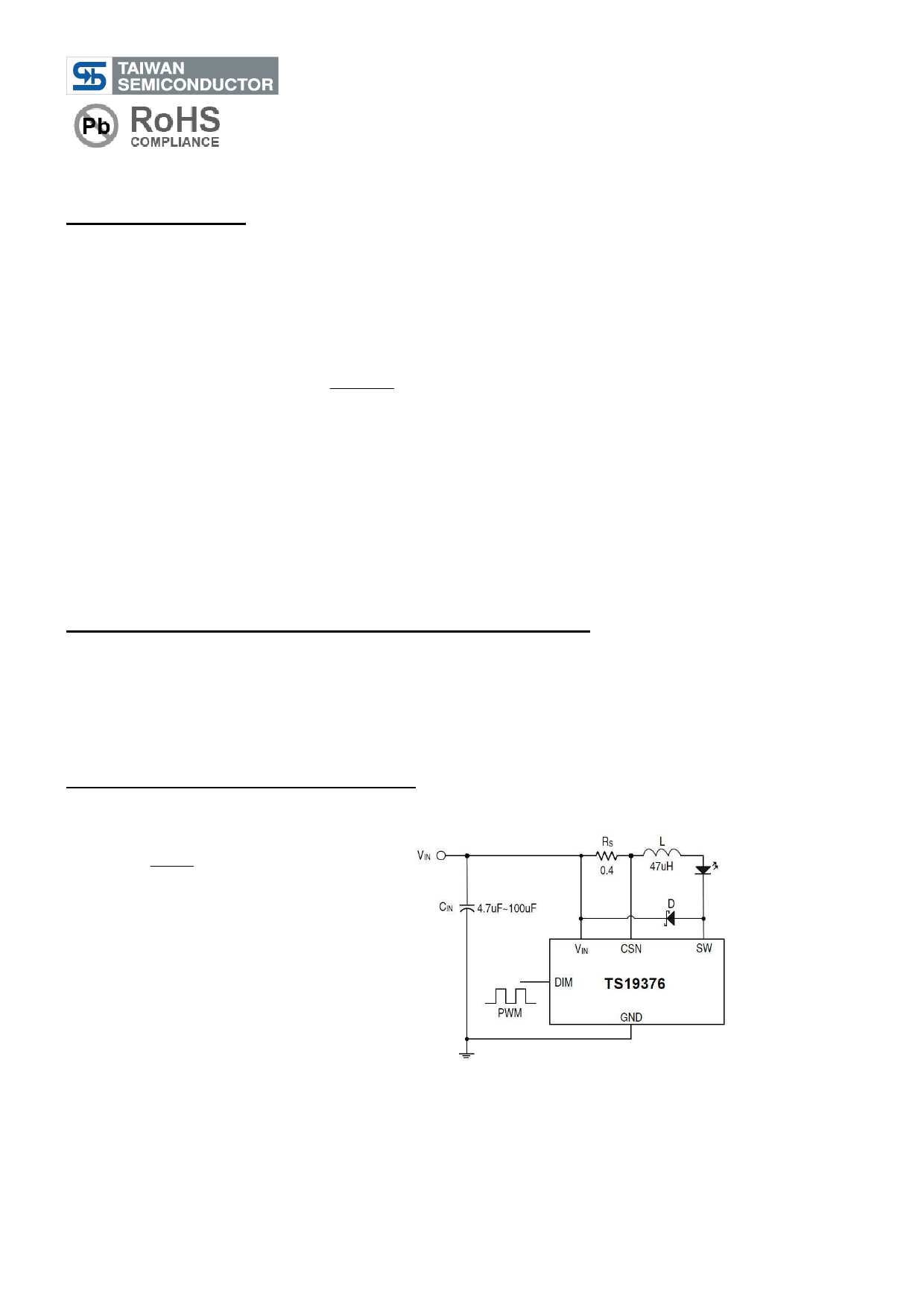
Output current adjustment by PWM control
A Pulse Width Modulated (PWM) signal with duty cycle PWM can be applied to the DIM pin, as shown below, to
adjust the output current to a value below the nominal average value set by resistor RS:
IOUT = 0.1× D
RS
(0≦D≦100%, 0.3V<Vpulse<2.5V)
PWM dimming provides reduced brightness by modulating the LED’s forward current between 0% and 100%. The
LED brightness is controlled by adjusting the relative ratios of the on time to the off time. A 25% brightness level is
achieved by turning the LED on at full current for 25% of one cycle. To ensure this switching process between on
and off state is invisible by human eyes, the switching frequency must be greater than 100 Hz. Above 100 Hz, the
human eyes average the on and off times, seeing only an effective brightness that is proportional to the LED’s on-
time duty cycle. The advantage of PWM dimming is that the forward current is always constant; therefore the LED
color does not vary with brightness as it does with analog dimming. Pulsing the current provides precise brightness
control while preserving the color purity. The dimming frequency of TS19376 can be as high as 20 kHz.
4/8
Version: A12
Share Link: 