CY14B108N-ZSP25XCT Ver la hoja de datos (PDF) - Cypress Semiconductor
Número de pieza
componentes Descripción
Fabricante
CY14B108N-ZSP25XCT Datasheet PDF : 24 Pages
| |||
CY14B108L, CY14B108N
Maximum Ratings
Exceeding maximum ratings may impair the useful life of the
device. These user guidelines are not tested.
Storage Temperature ..................................–65°C to +150°C
Maximum Accumulated Storage Time
At 150°C Ambient Temperature..........................1000h
At 85°C Ambient Temperature.................... ..20 Years
Ambient Temperature with
Power Applied .............................................–55°C to +150°C
Supply Voltage on VCC Relative to GND.......... –0.5V to 4.1V
Voltage Applied to Outputs
in High Z State....................................... –0.5V to VCC + 0.5V
Input Voltage .......................................... –0.5V to Vcc + 0.5V
Transient Voltage (<20 ns) on
Any Pin to Ground Potential.................. –2.0V to VCC + 2.0V
Package Power Dissipation
Capability (TA = 25°C) ....................................................1.0W
Surface Mount Pb Soldering
Temperature (3 Seconds)...........................................+260°C
DC Output Current (1 output at a time, 1s duration) ....15 mA
Static Discharge Voltage ......................................... > 2001V
(per MIL-STD-883, Method 3015)
Latch Up Current................................................... > 200 mA
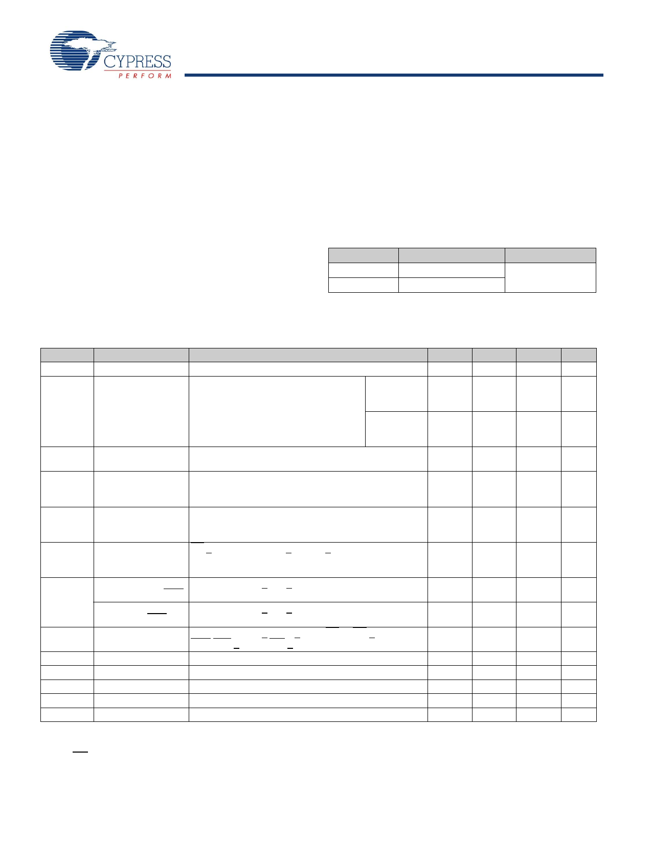
Operating Range
Range
Commercial
Industrial
Ambient Temperature
0°C to +70°C
–40°C to +85°C
VCC
2.7V to 3.6V
DC Electrical Characteristics
Over the Operating Range (VCC = 2.7V to 3.6V)
Parameter Description
Test Conditions
Min
VCC
Power Supply
2.7
ICC1
Average VCC Current tRC = 20 ns
Commercial
tRC = 25 ns
tRC = 45 ns
Values obtained without output loads Industrial
(IOUT = 0 mA)
ICC2
ICC3
ICC4
ISB
IIX[8]
IOZ
VIH
VIL
VOH
VOL
VCAP
Average VCC Current All Inputs Don’t Care, VCC = Max
during STORE
Average current for duration tSTORE
Average VCC Current All I/P cycling at CMOS levels.
at tRC= 200 ns,
Values obtained without output loads (IOUT = 0 mA).
VCC (Typ), 25°C
Average VCAP
Current during
AutoStore Cycle
All Inputs Don’t Care. Average current for duration
tSTORE
VCC Standby Current CE > (VCC – 0.2V). VIN < 0.2V or > (VCC – 0.2V). Standby
current level after nonvolatile cycle is complete.
Inputs are static. f = 0 MHz.
Input Leakage
VCC = Max, VSS < VIN < VCC
–2
Current (except HSB)
Input Leakage
Current (for HSB)
VCC = Max, VSS < VIN < VCC
–200
Off-State Output
VCC = Max, VSS < VOUT < VCC, CE or OE > VIH or
–2
Leakage Current
BHE/BLE > VIH or WE < VIL
Input HIGH Voltage
2.0
Input LOW Voltage
Output HIGH Voltage IOUT = –2 mA
Output LOW Voltage IOUT = 4 mA
Storage Capacitor Between VCAP pin and VSS, 5V Rated
Vss – 0.5
2.4
122
Typ[7]
3.0
40
150
Max Unit
3.6
V
70
mA
70
mA
55
mA
75
mA
75
mA
57
mA
20
mA
mA
10
mA
10
mA
+2
μA
+2
μA
+2
μA
VCC + 0.5 V
0.8
V
V
0.4
V
360
μF
Notes
7. Typical values are at 25°C, VCC= VCC (Typ). Not 100% tested.
8. The HSB pin has IOUT = -2 uA for VOH of 2.4V when both active HIGH and LOW drivers are disabled. When they are enabled standard VOH and VOL are valid. This
parameter is characterized but not tested.
Document #: 001-45523 Rev. *D
Page 8 of 24
[+] Feedback
Share Link: 