LC75106V Ver la hoja de datos (PDF) - ON Semiconductor
Número de pieza
componentes Descripción
Fabricante
LC75106V Datasheet PDF : 15 Pages
| |||
LC75106V
Specifications
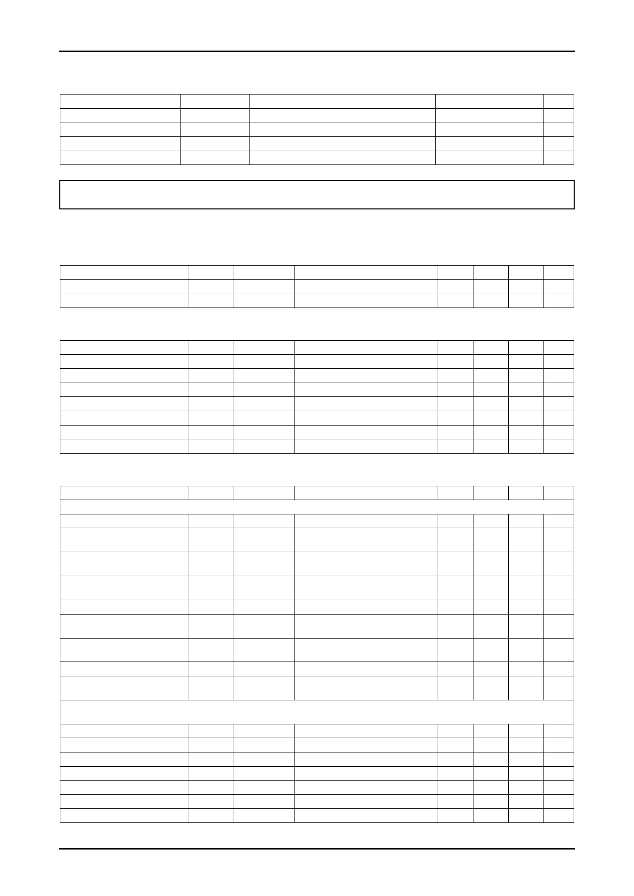
Absolute Maximum Ratings at Ta = 25°C, Analog GND = 0V
Parameter
Symbol
Conditions
Maximum power supply voltage
Allowable consumption power
VDD max
Pd max
VDD
Ta ≤ 70°C *
Operating temperature range
Ta
Storage temperature range
Tstg
* Mounted reference PCB (114.3mm × 76.1mm × 1.6mm, glass epoxy resin)
Ratings
unit
+8.0 to +10.0
V
500 mW
-20 to +70 °C
-40 to +125 °C
Stresses exceeding Maximum Ratings may damage the device. Maximum Ratings are stress ratings only. Functional operation above the Recommended Operating
Conditions is not implied. Extended exposure to stresses above the Recommended Operating Conditions may affect device reliability.
DC Electrical Characteristics Ratings at Ta = 25°C, VSS = 0V
Operating Condition/Ta = 25°C
Parameter
Recommended supply voltage
Range of operating supply voltage
Symbol
VDD
VDDopg
Pin name
VDD
VDD
Conditions
VDD=9.0V
min
8.0
typ
max
unit
9.0
V
10.0
V
Electric Characteristics/Ta = 25°C, VDD = 9.0V, fin = 1kHz, VIN = 1mVrms = 0dB, RL = 10kΩ
Parameter
Current without signal
Clock frequency
Control data Hi Level voltage
Control data Low Level voltage
Control data Input pulse width
Symbol
IDDO
FCLK
VIH
VIL
tφW
Pin name
VDD
OSC
SCL, SDA
SCL, SDA
SCL, SDA
Conditions
OSC Ex.R=30kΩ
min
typ
1.72
2.45
2.0
0.0
1.0
Control data Hold time
thold
SCL, SDA
1.0
Control data Operation frequency fopg
SCL, SDA
max
60
3.19
3.5
0.5
500
unit
mA
MHz
V
V
μs
μs
kHz
AC Electrical Characteristics (Reference data: No measurement)
Parameter
Symbol
Pin name
Conditions
min
typ
max
unit
[Mic-AMP] Input=MICIN1/MICIN2, Output=MICOUT1/MICOUT2, VIN=-48dBV, VALC=VREF – 1.414V, Mic-AMP NF Ex.R=680Ω, ALC Ex.C=2.2μF
Mic Gain
VGM2
MICOUT1/2
Mic-AMP NF Ex.R=680Ω
+34.0 +37.0 +42.0 dB
Max output voltage
VoTM
MICOUT1/2
Mic Gain=+38dB, THD=1%,
1.75
Filter=A-filter, ALC=OFF
Vrms
Total harmonic distortion rate1
Total harmonic distortion rate 2
Output noise voltage
ALC attack time
ALC release time
Input impedance
THDM1
THDM2
VNOM
TaA
TaR
ZiM
MICOUT1/2
MICOUT1/2
MICOUT1/2
MICOUT1/2
MICOUT1/2
MICIN1/2
Mic Gain=+38dB, ALC=OFF,
VO=-10dBV, Filter=A-filter
Mic Gain=+38dB, ALC=ON, VO=0dBV,
VIN=-32dBV, Filter=A-filter
Mic Gain=+38dB, Filter=A-filter
Mic Gain=+38dB, ALC=ON, VO=0dBV,
VIN=-32dBV
Mic Gain=+38dB, ALC=ON, VO=0dBV,
VIN=-32dBV
0.07
0.5 %
0.1
1.0 %
-74.0
60
-65.0 dBV
ms
6.0
s
45
60
75 kΩ
Output impedance
ZoM
MICOUT1/2
Mic-Gain=+38dB, ALC=OFF,
VO=0dBV
0.75
1.5
3.0
[Digital ECHO] Stereo signal outside connection modes, Input=SUMIN, Output=ECHOOUT, VIN=-10dBV, Delay Time=100ms, Mic Volume 1/2=0dB,
Feedback Volume=-∞
Delay time
DT
ECHOOUT
FCLK=2.45MHz
75
100
125
Output Gain
VGE
ECHOOUT
-4.5
-2.0
+0.5
Max output voltage
VoE
ECHOOUT
THD=10%, Filter=A-filter
1.5
Total harmonic distortion rate
THDE
ECHOOUT
Filter=A-filter
0.7
2.0
Output noise voltage
VNOE
ECHOOUT
Filter=A-filter
-65
-55
Input impedance
ZiE
SUMIN
45
60
75
Output impedance
ZoE
ECHOOUT
Delay time=100ms, VO=0dBV
45
60
75
kΩ
ms
dB
Vrms
%
dBV
kΩ
kΩ
Continued to the next page.
No. A2153-2/15
Share Link: 