P6KE Ver la hoja de datos (PDF) - STMicroelectronics
Número de pieza
componentes Descripción
Fabricante
P6KE Datasheet PDF : 9 Pages
| |||
Characteristics
P6KE
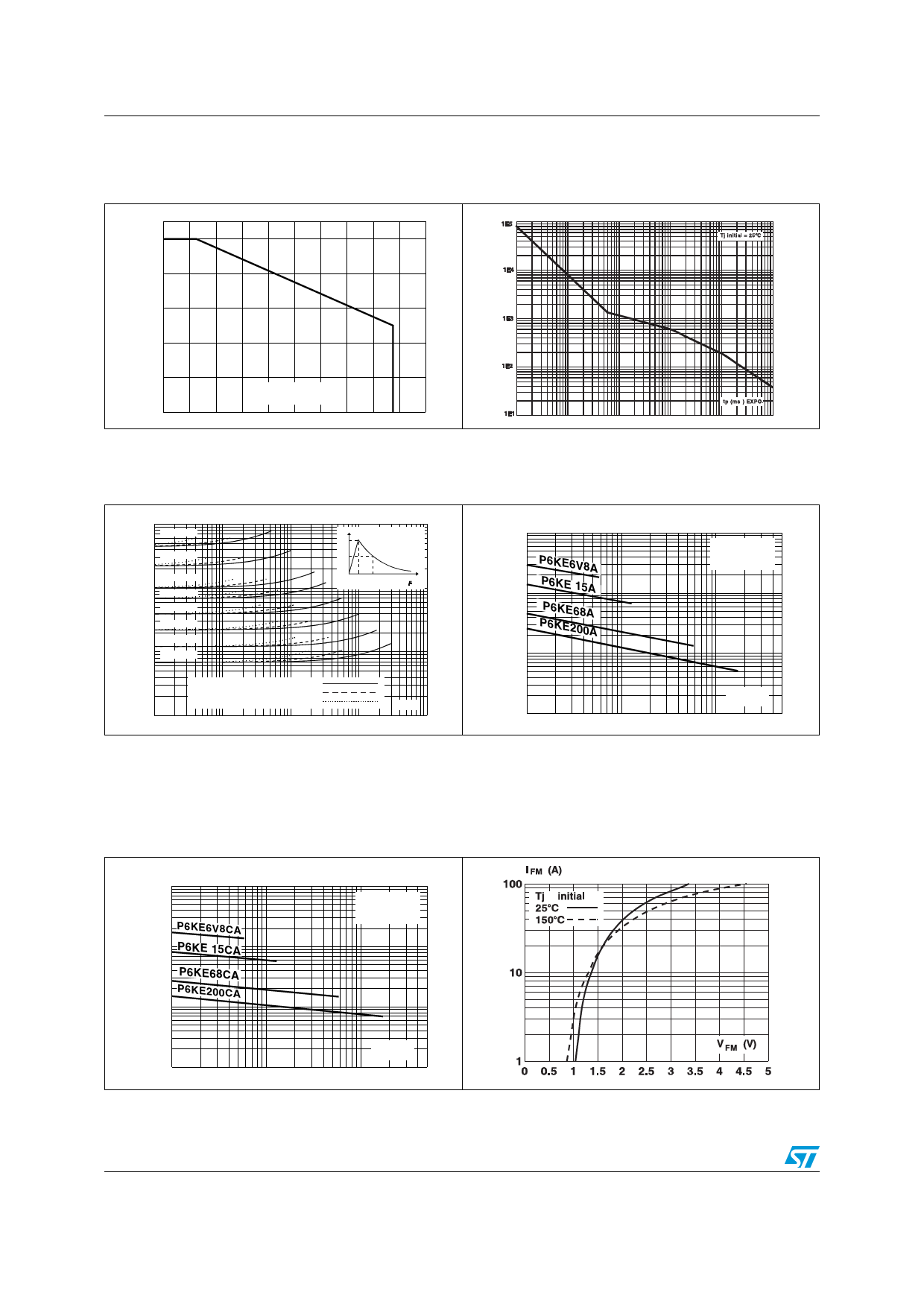
Figure 3.
%
100
Peak power dissipation vs. initial
junction temperature
(printed circuit board)
Figure 4. Peak pulse power vs. exponential
pulse duration.
Ppp (W)
80
60
40
20
0
0
Tj initialø(°C)
20 40 60 80 100 120 140 160 180 200
0.001
0.01
0.1
1
10
100
Figure 5. Clamping voltage vs. peak pulse
current(1)
VCL (V)
1000
P6KE 440A
P6KE 220A
P6KE 100A
100
P6KE 68A
P6KE 39A
P6KE 22A
P6KE 12A
10 P6KE 6V8A
% Ipp
100
Tj initial = 25°øC
50
0
t
tr tp
t r < 10 s
Figure 6.
Capacitance vs. reverse applied
voltage for unidirectional types
(typical values).
C (pF)
10000
1000
P6KE6V8A
P6KE 15A
P6KE68A
P6KE200A
100
Tj = 25°øC
F= 1 MHz
Exponential waveform: tp = 20µs
tp = 1ms
tp = 10ms
1
0.1
1
10
Ipp (A)
100
1000
10
1
V R (V)
10
100
500
1. The curves in Figure 5 are specified for a junction temperature of 25°C before surge. The given results may be
extrapolated for other junction temperatures by using the following formula : ΔVBR = αT x [Tamb -25] x VBR(25°C)
For intermediate voltages, extrapolate the given results.
Figure 7.
Capacitance vs. reverse applied
voltage for bidirectional types
(typical values).
C (pF)
10000
P6KE6V8CA
1000 P6KE 15CA
P6KE68CA
P6KE200CA
100
Tj = 25°øC
F= 1 MHz
Figure 8.
Peak forward voltage drop vs. peak
forward current for unidirectional
types (typical value).(1)
V R (V)
10
1
10
100
500
1. Multiply by 2 for units with VBR > 220 V.
4/9
Doc ID 3068 Rev 7
Share Link: 