M54679FP Ver la hoja de datos (PDF) - MITSUBISHI ELECTRIC
Número de pieza
componentes Descripción
Fabricante
M54679FP Datasheet PDF : 9 Pages
| |||
PRELIMINARY
Notice: This is not a final specification.
Some parametric limits are subject to change.
MITSUBISHI <CONTROL / DRIVER IC>
M54679FP
2-PHASE STEPPER MOTOR DRIVER
(6). Spike current cancellation.
Output power transistors go to ON, then the spike current
appears on the RS (current sensing) in a short time and this is
caused by the internal delay time.
M54679FP has the cancellation circuit of the spike current as
the current sensing comparators do not cause error functions.
So, the function of current sensing comparators are shut off
during 2µs since the output power transistors go to ON.
(7). Ph signal delay circuit.
M54679FP has a delay time of 3.0µs until output H-bridge
power stage go to ON since Ph signal change Low to high.
This delay time is enough short time for the frequency (plus
rate) of Ph signal and there is no problem in the normal
function.
(8). Rs and S1 or S2 terminal.
If S1 or S2 terminal (non-inverted input of the current sensing
comparators) is connected the nearest position of current
sensing resistor, the error of the current sensing by means of
wire resistance on the board will be decreased.
(9). Voltage stabilizer.
M54679FP has a voltage stabilizer of 3.5V.
The reference voltage (Vref) can connect the output (Regout)
of voltage stabilizer directly.
In this case, the current capability of the output of voltage
stabilizer is 1.0mA (source current), 0.1mA (sink current).
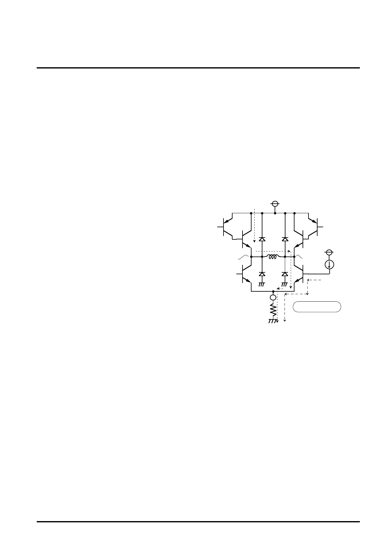
(10). Setting output current.
As the output circuit of M54679FP is designed by the bipolar
type NPN transistors, the current that go through the motor
coil is smaller about 15mA (typical) than the current that go
through the current sensing resistor.
This is caused by the base current of the power transistors.
Therefore, be aware this base current when the output
current is set.
(11). Power GND terminal.
Power GND is connected the anodes of flywheel diodes of
bottom side.
When the output H-bridge power stage goes to ON, as the
flyback current go through this GND terminal, minimize the
wire resistor of this GND on the board.
VM
ON
Iout
MA
OFF
RS
OFF VCC
MB
ON
Ib = 15mA (Typ.)
Iout = IRS - Ib
Share Link: 