AAT1162 Ver la hoja de datos (PDF) - Skyworks Solutions
Número de pieza
componentes Descripción
Fabricante
AAT1162 Datasheet PDF : 19 Pages
| |||
The external resistors set the output voltage according
to the following equation:
VOUT
=
0.6V
⎛⎝1
+
R1 ⎞
R2 ⎠
or
R1
=
⎛ VOUT
⎝ VREF
-1⎞⎠
·
R2
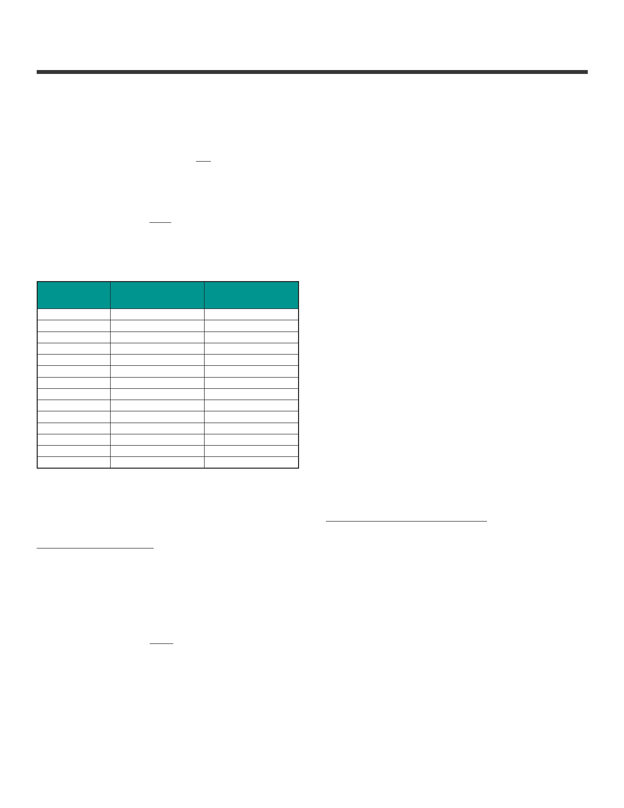
Table 1 shows the resistor selection for different output
voltage settings.
VOUT (V)
0.8
0.9
1.0
1.1
1.2
1.3
1.4
1.5
1.8
1.85
2.0
2.5
3.3
5.0
R2 = 5.9(kΩ)
R1 (kΩ)
1.96
2.94
3.92
4.99
5.90
6.81
7.87
8.87
11.8
12.4
13.7
18.7
26.7
43.2
R2 = 59(kΩ)
R1 (kΩ)
19.6
29.4
39.2
49.9
59.0
68.1
78.7
88.7
118
124
137
187
267
432
Table 1: Resistor Selection for Different Output
Voltage Settings. Standard 1% Resistors are
Substituted for Calculated Values.
Inductor Selection
For most designs, the AAT1162 operates with inductors
of 2μH to 4.7μH. Low inductance values are physically
smaller, but require faster switching, which results in
some efficiency loss. The inductor value can be derived
from the following equation:
L1 =
VOUT
3.3
· 3.8µH
DATA SHEET
AAT1162
12V, 1.5A Step-Down DC/DC Converter
Where ∆IL is inductor ripple current. Large value induc-
tors lower ripple current and small value inductors result
in high ripple currents. Choose inductor ripple current
approximately 32% of the maximum load current 1.5A,
or ∆IL = 480mA. For output voltages above 3.3V, the
minimum recommended inductor is 3.8μH. For 3.3V and
below, use a 2 to 3.8μH inductor. For optimum voltage-
positioning load transients, choose an inductor with DC
series resistance in the 15mΩ to 20mΩ range. For
higher efficiency at heavy loads (above 1A), or minimal
load regulation (but some transient overshoot), the
resistance should be kept below 18mΩ. The DC current
rating of the inductor should be at least equal to the
maximum load current plus half the ripple current to
prevent core saturation (1.5A + 280mA). Table 2 lists
some typical surface mount inductors that meet target
applications for the AAT1162.
Manufacturer’s specifications list both the inductor DC
current rating, which is a thermal limitation, and the
peak current rating, which is determined by the satura-
tion characteristics. The inductor should not show any
appreciable saturation under normal load conditions.
Some inductors may meet the peak and average current
ratings yet result in excessive losses due to a high DCR.
Always consider the losses associated with the DCR and
its effect on the total converter efficiency when selecting
an inductor. For example, the 4.7μH WE-TPC series
inductor selected from Wurth has an 38mΩ DCR and a
2.4ADC current rating. At full load, the inductor DC loss
is 85mW which gives only a 1.1% loss in efficiency for a
1.5A, 5V output.
Input Capacitor Selection
The input capacitor reduces the surge current drawn
from the input and switching noise from the device. The
input capacitor impedance at the switching frequency
shall be less than the input source impedance to prevent
high frequency switching current passing to the input. A
low ESR input capacitor sized for maximum RMS current
must be used. Ceramic capacitors with X5R or X7R
dielectrics are highly recommended because of their low
ESR and small temperature coefficients. A 10μF ceramic
capacitor is sufficient for most applications.
Skyworks Solutions, Inc. • Phone [781] 376-3000 • Fax [781] 376-3100 • sales@skyworksinc.com • www.skyworksinc.com
201998B • Skyworks Proprietary Information • Products and Product Information are Subject to Change Without Notice. • March 20, 2013
11
Share Link: 