PI74AVC16834 Ver la hoja de datos (PDF) - Pericom Semiconductor Corporation
Número de pieza
componentes Descripción
Fabricante
PI74AVC16834 Datasheet PDF : 10 Pages
| |||
PI74AVC16834
18-Bit Universal Bus Driver
with 3-State Outputs 1122334455667788990011223344556677889900112233445566778899001122112233445566778899001122334455667788990011223344556677889900112211223344556677889900112233445566778899001122334455667788990011221122334455667788990011223344556677889900112233445566778899001122112233445566778899001122
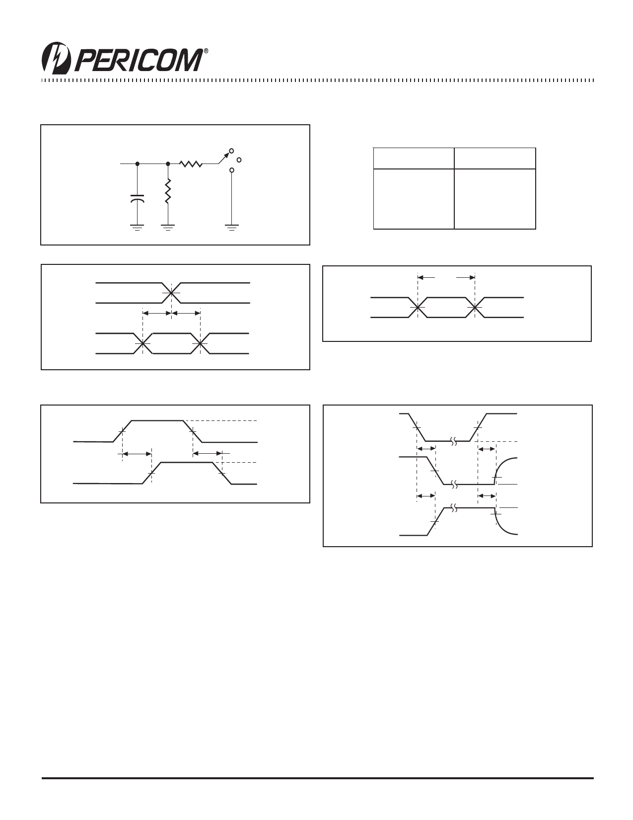
Parameter Measurement Information (VCC = 3.3V ±0.3V)
From Output
Under Test
CL=50pF
5007
S1
2 x VCC
Open
GND
5007
TEST
tpd
tPLZ/tPZL
tPHZ/tPZH
S1
Open
2 x VCC
GND
Load Circuit
Timing
Input
Data
Input
VCC/2
tsu
th
VCC/2
VCC/2
VCC
0V
VCC
0V
Voltage Waveforms
Setup and Hold Times
Input
tW
VCC/2
VCC/2
VCC
0V
Voltage Waveforms
Pulse Duration
Input
Vcc/2
tPLH
Output
Vcc/2
Vcc/2
tPLH
Vcc/2
VCC
0V
VOH
VOL
Voltage Waveforms
Propagation Delay Times
Output
Control
(Low-level
enabling)
Output
Waveform 1
S1 at 2 x VSS
Output
Waveform 2
S1 at GND
VCC/2
tPZL
VCC/2
tPZH
VCC/2
VCC
VCC/2
0V
tPLZ
VCC
VOL +0.3V
VOL
tPHZ
VOH
VOH –0.3V
0V
Voltage Waveforms
Notes:
Enable and Disable Times
• CL includes probe and jig capacitance.
• Waveform 1 is for an output with internal conditions such that the output is LOW except when disabled by the output control.
• Waveform 2 is for an output with internal conditions such that the output is HIGH except when disabled by the output control.
• All input pulses are supplied by generators having the following characteristics: PRR ≤ 10 MHz, ZO = 50Ω, tr ≤2ns, tr ≤2ns.
• The outputs are measured one at a time with one transition per measurement.
• tPLZ and tPHZ are the same as tdis.
• tPZL and tPZH are the same as tdis.
• tPLH and tPHL are the same as tdis.
Figure 3. Load Circuit and Voltage Waveforms
09-0003
9
PS8376G 10/27/09
Share Link: 