854110AKILF Ver la hoja de datos (PDF) - Integrated Device Technology
Número de pieza
componentes Descripción
Fabricante
854110AKILF Datasheet PDF : 21 Pages
| |||
ICS854110I Data Sheet
2.5V DIFFERENTIAL LVDS CLOCK BUFFER
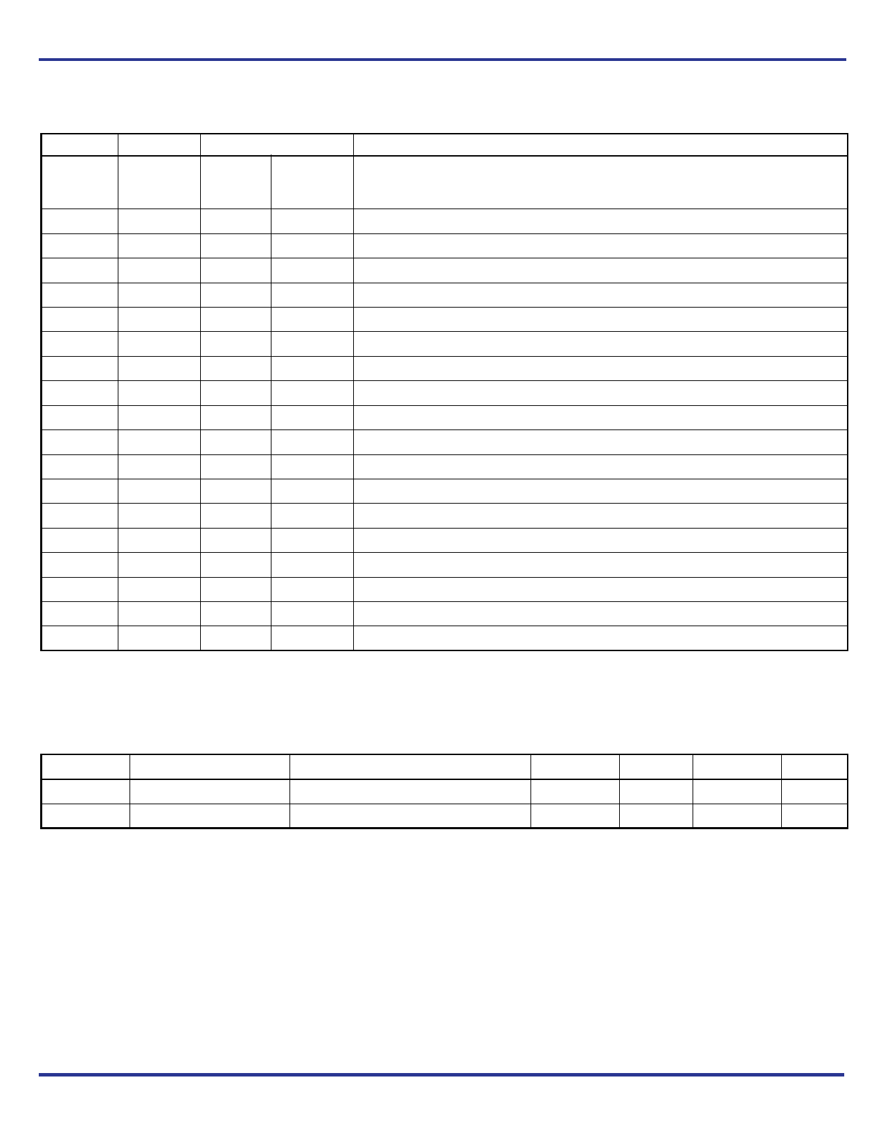
Table 1. Pin Descriptions
Number
1
2
3
4
5, 9, 25
6
7
8
10, 11
12, 13
14, 15
16, 32
17, 18
19, 20
21, 22
23, 24
26, 27
28, 29
30, 31
Name
ISET
CLK_SEL
CLK0
nCLK0
GND
CLK1
nCLK1
nOE
nQ9, Q9
nQ8, Q8
nQ7, Q7
VDD
nQ6, Q6
nQ5, Q5
nQ4, Q4
nQ3, Q3
nQ2, Q2
nQ1, Q1
nQ0, Q0
Type
Input
Input
Input
Power
Input
Input
Input
Output
Output
Output
Power
Output
Output
Output
Output
Output
Output
Output
Pulldown
Pulldown
Description
An external fixed resistor (RSET) from this pin to ground is needed to provide a
reference current for setting the slew rate of the differential outputs Q[0:9], nQ[0:9].
See Table 3C for function.
Input clock select. See Table 3A for function. LVCMOS/LVTTL interface levels.
Non-inverting clock/data input 0.
Inverting differential clock input 0.
Power supply ground.
Non-inverting clock/data input 1.
Inverting differential clock input 1.
Output enable. See Table 3B for function. LVCMOS/LVTTL interface levels.
Differential output pair 9. LVDS interface levels.
Differential output pair 8. LVDS interface levels.
Differential output pair 7. LVDS interface levels.
Power supply pins.
Differential output pair 6. LVDS interface levels.
Differential output pair 5. LVDS interface levels.
Differential output pair 4. LVDS interface levels.
Differential output pair 3. LVDS interface levels.
Differential output pair 2. LVDS interface levels.
Differential output pair 1. LVDS interface levels.
Differential output pair 0. LVDS interface levels.
NOTE: Pulldown refers to an internal input resistor. See Table 2, Pin Characteristics, for typical values.
Table 2. Pin Characteristics
Symbol
CIN
RPULLDOWN
Parameter
Input Capacitance
Input Pulldown Resistor
Test Conditions
Minimum
Typical
4
51
Maximum
Units
pF
kΩ
ICS854110AKI REVISION B JANUARY 27, 2011
2
©2011 Integrated Device Technology, Inc.
Share Link: 