SACB5.0 Ver la hoja de datos (PDF) - StarHope
Número de pieza
componentes Descripción
Fabricante
SACB5.0 Datasheet PDF : 4 Pages
| |||
SPSEMI
SACB(500W) Series
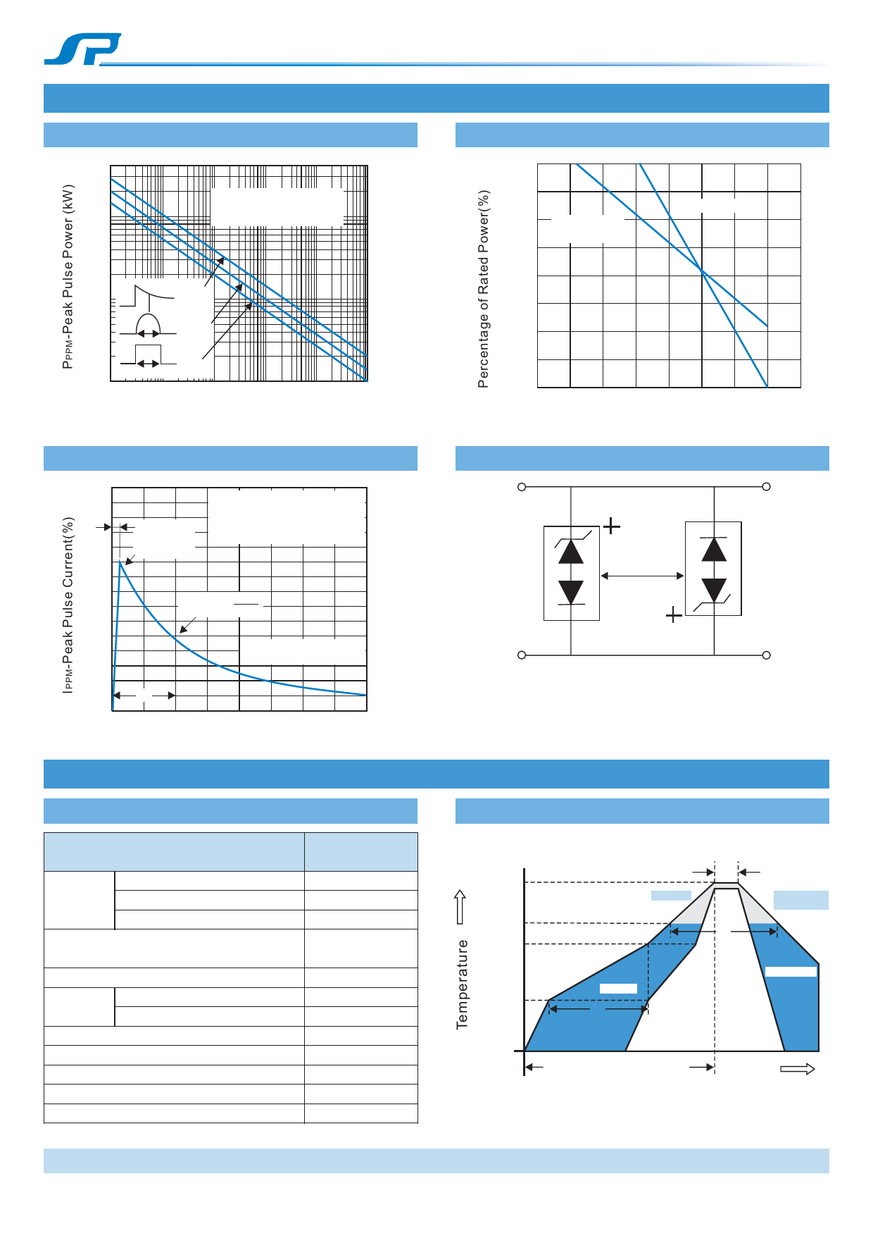
Characteristic Curves (TA=25 ℃ unless otherwise noted)
Fig.1 Peak Pulse Power Rating
Fig.2 Power Derating Curve
30
100
Non-Repetitive Pulse
Waveform shown in Fig. 3
10
TA = 25 °C
75 Peak Power
(single pulse)
Average Power
Exponentia
1 P td
P td Half SINE
P td Square
0.1
0.1μs 1.0μs
10μs
100μs 1.0ms
td - Pulse Width (sec.)
10ms
50
25
0
0 25 50 75 100 125 150 175 200
TL-Lead Temperature(℃)
Fig.3 Pulse Waveform
150
100
50
tr=10uS
Peak Value
IPPM
TJ=25℃
Pulse width(td) is defined
ad the Point where the Peak
Current Decays to 50% of IPPM
Half
Value
IPPM
2
10/1000μsec.Waveform
as defined by R.E.A
td
00
1.0
2.0
3.0
4.0
t-Time(mS)
Recommended Soldering Conditions
Recommended Conditions
Re”ow Condition
Pre Heat
-Temperature Min(T s(min))
-Temperature Max(T s(max))
-Time(Min to Max)(t s)
Average ramp up rate
(Liquidus Temp(TL) to peak)
Ts(max) to TL -Ramp-up Rate
Re”ow
-Temperature(TL)(Liquidus)
-Temperature(tL)
Peak Temp(TP)
Time within 5℃ of actual Peak Temp(tP)
Ramp-down Rate
Time 25℃ to Peak Temp(TP)
Do not exceed
Pb-Free assembly
(see Fig.1)
+150℃
+200℃
60-180secs
3℃/sec.Max.
3℃/sec.Max.
+217℃
60-150secs
+260(+0/-5)℃
30 secs.Max.
6℃/sec.Max.
8 min.Max.
+260℃
Fig.4 AC Line Protection Application
Low Capacitance
TVS
Application Note: Device must be used
with two units in parallel,opposite in polarity
as shown in circuit for AC signal line
protection.
Reflow Soldering
TP
TL
Ts(max)
Ts(min)
tP
Ramp-up
tL
Preheat
ts
Critical Zone
TL to TP
Ramp-down
25
time to peak temperature
(t 25℃ to peak)
Time
REV.2016.08.10
www.spsemi.cn
Page 3 of 4
Share Link: 