MAX1232CWE Ver la hoja de datos (PDF) - Maxim Integrated
Número de pieza
componentes Descripción
Fabricante
MAX1232CWE Datasheet PDF : 8 Pages
| |||
MAX1232
Microprocessor Monitor
Detailed Description
Power Monitor
A voltage detector monitors VCC and holds the reset
outputs (RST and RST) in their active states whenever
VCC is below the selected 5% or 10% tolerance (4.62V
or 4.37V, typically). To select the 5% level, connect TOL
to ground. To select the 10% level, connect TOL to VCC.
The reset outputs will remain in their active states until
VCC has been continuously in-tolerance for a minimum of
250ms (the reset active time) to allow the power supply
and μP to stabilize.
The RST output both sinks and sources current, while the
RST output, an open-drain MOSFET, sinks current only
and must be pulled high.
Pushbutton Reset Input
The MAX1232’s debounced manual reset input (PBRST)
manually forces the reset outputs into their active states.
The reset outputs go active after PBRST has been held
low for a time tPBD, the pushbutton reset delay time. The
reset outputs remain in their active states for a minimum
of 250ms after PBRST rises above VIH (Figure 3).
A mechanical pushbutton or an active logic signal can
drive the PBRST input. The debounced input ignores
input pulses less than 1ms and is guaranteed to recog-
nize pulses of 20ms or greater. The PBRST input has
an internal pullup to VCC of about 100μA; therefore, an
external pullup resistor is not necessary.
Watchdog Timer
The microprocessor drives the ST input with an input/
output (I/O) line. The microprocessor must toggle the ST
input within a set period (as determined by TD) to verify
proper software execution. If a hardware or software fail-
ure keeps ST from toggling within the minimum timeout
period—ST is activated only by falling edges (a high-to-
low transition)—the MAX1232 reset outputs are forced to
their active states for 250ms (Figure 2). This typically initi-
ates the microprocessor’s power-up routine. If the inter-
ruption continues, new reset pulses are generated each
timeout period until ST is strobed. The timeout period is
determined by the TD input connection. This timeout peri-
od is typically 150ms with TD connected to GND, 600ms
with TD floating, or 1200ms with TD connected to VCC.
The software routine that strobes ST is critical. The code
must be in a section of software that executes frequently
enough so the time between toggles is less than the
watchdog timeout period. One common technique con-
trols the microprocessor I/O line from two sections of the
program. The software might set the I/O line high while
operating in the foreground mode, and set it low while in
the background or interrupt mode. If both modes do not
execute correctly, the watchdog timer issues reset pulses.
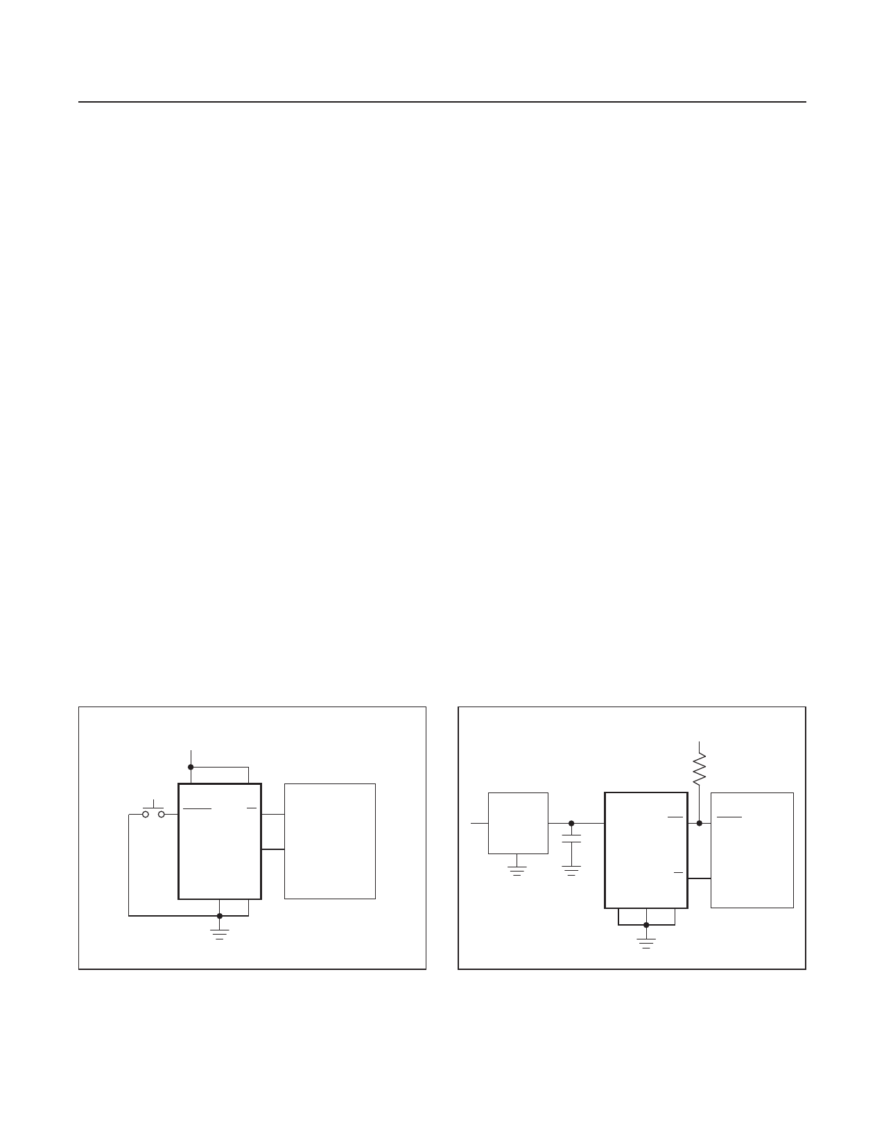
+5V
VCC
TD
PB RST
ST
MAX1232
RST
I/O
MICROPROCESSOR
RESET
GND TOL
+5V
10kΩ
+8V
7805
3-TERMINAL
+5V
VCC
RST
REGULATOR
0.10µF MAX1232
ST
TD TOL GND
RESET
MICROPROCESSOR
I/O
Figure 1. Pushbutton Reset
Figure 2. Watchdog Timer
www.maximintegrated.com
Maxim Integrated │ 4
Share Link: 