CXA1597M Ver la hoja de datos (PDF) - Sony Semiconductor
Número de pieza
componentes Descripción
Fabricante
CXA1597M Datasheet PDF : 22 Pages
| |||
CXA1597M/P
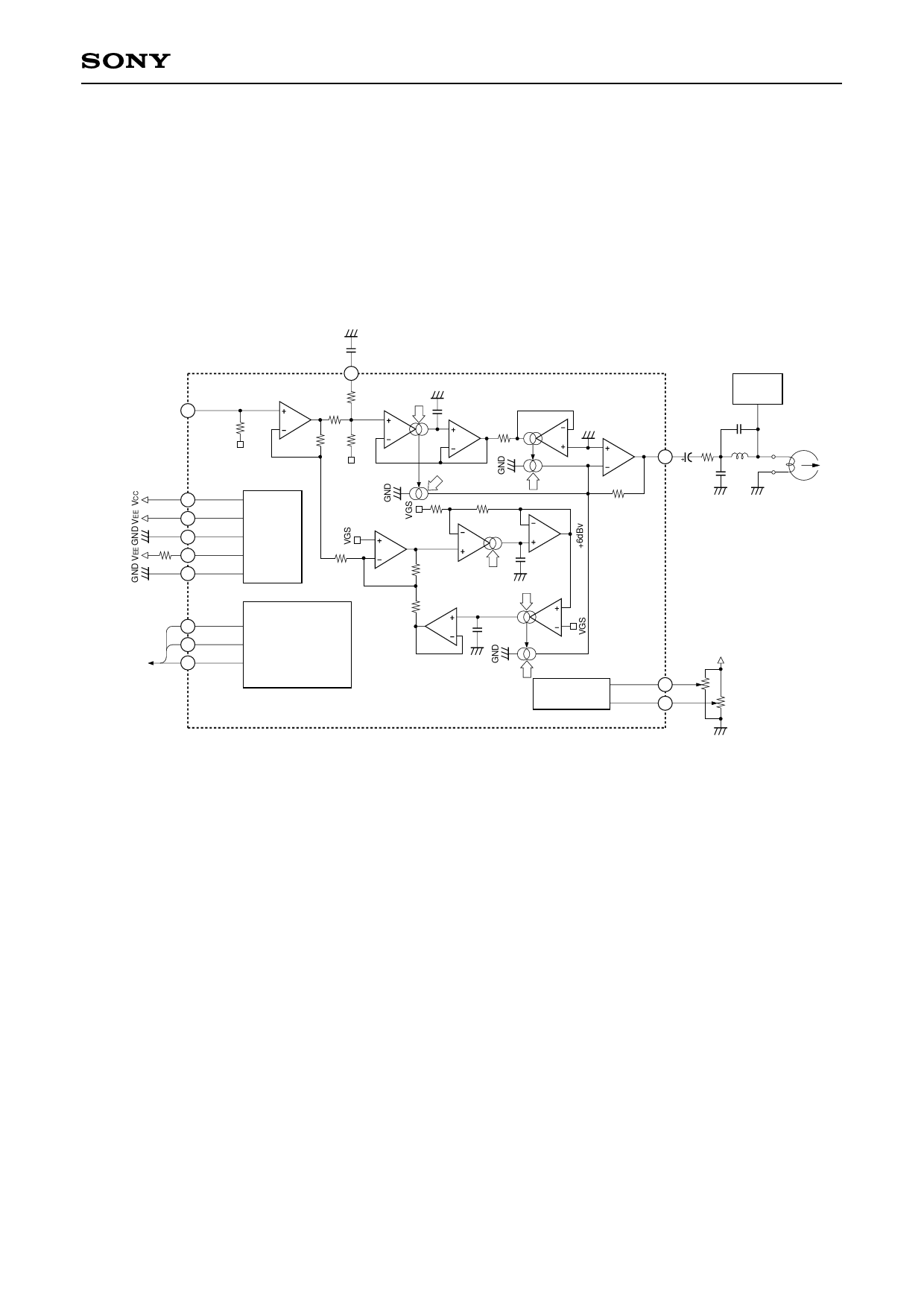
Description of Operation
1. Recording equalizer amplifier
The primary features of the CXA1597 recording equalizer amplifier are that by taking full advantage of
monolithic filter technology, an LC resonance circuit consisting of a coil and capacitor normally required for
high frequency compensation is dispensed with and medium and low-frequency sensitivity compensation is
performed with its internal filter alone.
This IC has the circuit configuration shown in Fig. 1 to provide the optimum frequency response required for
recording equalizer amplifiers.
GND
C1
0.47µ
R1 27k
to Control IC
REC IN
–18.5dBv
R1
50k
VGS
VCC
VEE
GND (VG)
IREF
DGND
TAPE EQ
REC MUTE
SPEED
R4
0dBv5.5k
OP2
R3 R7
35k 34k
BOOST
R8
4.8k
–7dBv
Gm2
GND
IfM
C2
200p
R11
–7dBv 40k
×1
VGS
IGH
Gm5
GND
REC OUT
–3dBv
OP4
IGL
R13
50k
R10
R9
BIAS
8k
24k
×1
–6dBv
Gm3
OP3
C4
R2
5k
R6
100p
20k
If/Q
–6dBv
R5
20k
×1
GND
IfQ
C3
100p
Gm4
CONTROL
GND
IGP
CALIBRATION
REC CAL
Gp CAL
Bias
OSC
C7
75p
R14 L1
12k 27mH
C5
C6
3.3µ
150p
GND GND
DVCC
R15
50k
R16
50k
REC HEAD
GND
Fig. 1. CXA1597 functional circuit block diagram
The symbols (Gm2, Gm3, Gm4, Gm5) shown in Fig. 1 denote "voltage → current converter circuits" and
"multiplier circuits."
The "voltage → current converter circuits" convert the voltage between the positive and negative input pins into
current by using the IC's internal resistance. The "multiplier circuits" multiply the current generated by the
"voltage → current converter circuits" with a coefficient.
The recording equalizer amplifier requires the six parameters shown in Fig. 2 (GL, GH, GP, fM, fP, and Q) to
implement its frequency response. These parameters are controlled by each control current shown in Fig. 1
(IGL, IGH, IGP, IfM, If/Q, and IfQ).
Therefore, the CXA1597 reduces fluctuations caused by the temperature characteristics and unevenness of its
internal resistance by using currents which are independent of the internal resistance (currents which depend
on external resistance) and those which are dependent on the internal resistance.
This IC uses currents dependent on the internal resistance where equalizer amplifier gain is determined and
currents dependent on external resistance where the filter time constant is determined. This is because the
generatrix of the coefficient for the "multiplier circuits" is generated in the IC so that it depends on the internal
resistance. Consequently, the gain relationship of GL, GH and GP is such that because the current obtained by
the "voltage → current converter circuits" is converted into voltage by the I-V amplifier in the final stage of Fig.
1, the control currents are controlled by currents dependent on the internal resistance. In this way, the
coefficients for conversion [voltage → current → voltage] all become ratios to the internal resistance, so that
the fluctuations of temperature characteristics and unevenness are reduced.
– 10 –
Share Link: 