HV830X Ver la hoja de datos (PDF) - Supertex Inc
Número de pieza
componentes Descripción
Fabricante
HV830X Datasheet PDF : 4 Pages
| |||
HV830
External Component Description
External Component
Diode
Cs Capacitor
REL-osc
RSW-osc
CSW Capacitor
Lx Inductor
Lamp
Selection Guide Line
Fast reverse recovery diode, BAS21LT1 or equivalent.
0.01µF to 0.1µF, 200V capacitor to GND is used to store the energy transferred from the inductor.
The EL lamp frequency is controlled via an external REL resistor connected between REL-osc and VDD of the
device. The lamp frequency increases as REL decreases. As the EL lamp frequency increases, the amount
of current drawn from the battery will increase and the output voltage VCS will decrease. The color of the EL
lamp is dependent upon its frequency.
A 3.3MΩ resistor would provide lamp frequency of 220 to 280Hz. Decreasing the REL-osc by a factor of 2 will
increase the lamp frequency by a factor of 2.
The switching frequency of the converter is controlled via an external resistor, RSW between RSW-osc and VDD
of the device. The switching frequency increases as RSW decreases. With a given inductor, as the switching
frequency increases, the amount of current drawn from the battery will decrease and the output voltage, VCS,
will also decrease.
A 1nF capacitor is recommended on RSW-osc to GND when a 0.01µF CS capacitor is used. This capacitor
is used to shunt any switching noise that may couple into the RSW-osc pin. The CSW capacitor may also be
needed when driving large EL lamp due to an increase in switching noise.
The inductor Lx is used to boost the low input voltage by inductive flyback. When the internal switch is on,
the inductor is being charged. When the internal switch is off, the charge stored in the inductor will be
transferred to the high voltage capacitor CS. The energy stored in the capacitor is connected to the internal
H-bridge and therefore to the EL lamp. In general, smaller value inductors, which can handle more current,
are more suitable to drive larger size lamps. As the inductor value decreases, the switching frequency of the
inductor (controlled by RSW) should be increased to avoid saturation.
220µH Murata inductors with 5.4Ω series DC resistance is typically recommended. For inductors with the
same inductance value but with lower series DC resistance, lower RSW value is needed to prevent high current
draw and inductor saturation.
As the EL lamp size increases, more current will be drawn from the battery to maintain high voltage across
the EL lamp. The input power, (VIN x IIN), will also increase. If the input power is greater than the power
dissipation of the package (400mW), an external resistor in series with one side of the lamp is recommended
to help reduce the package power dissipation.
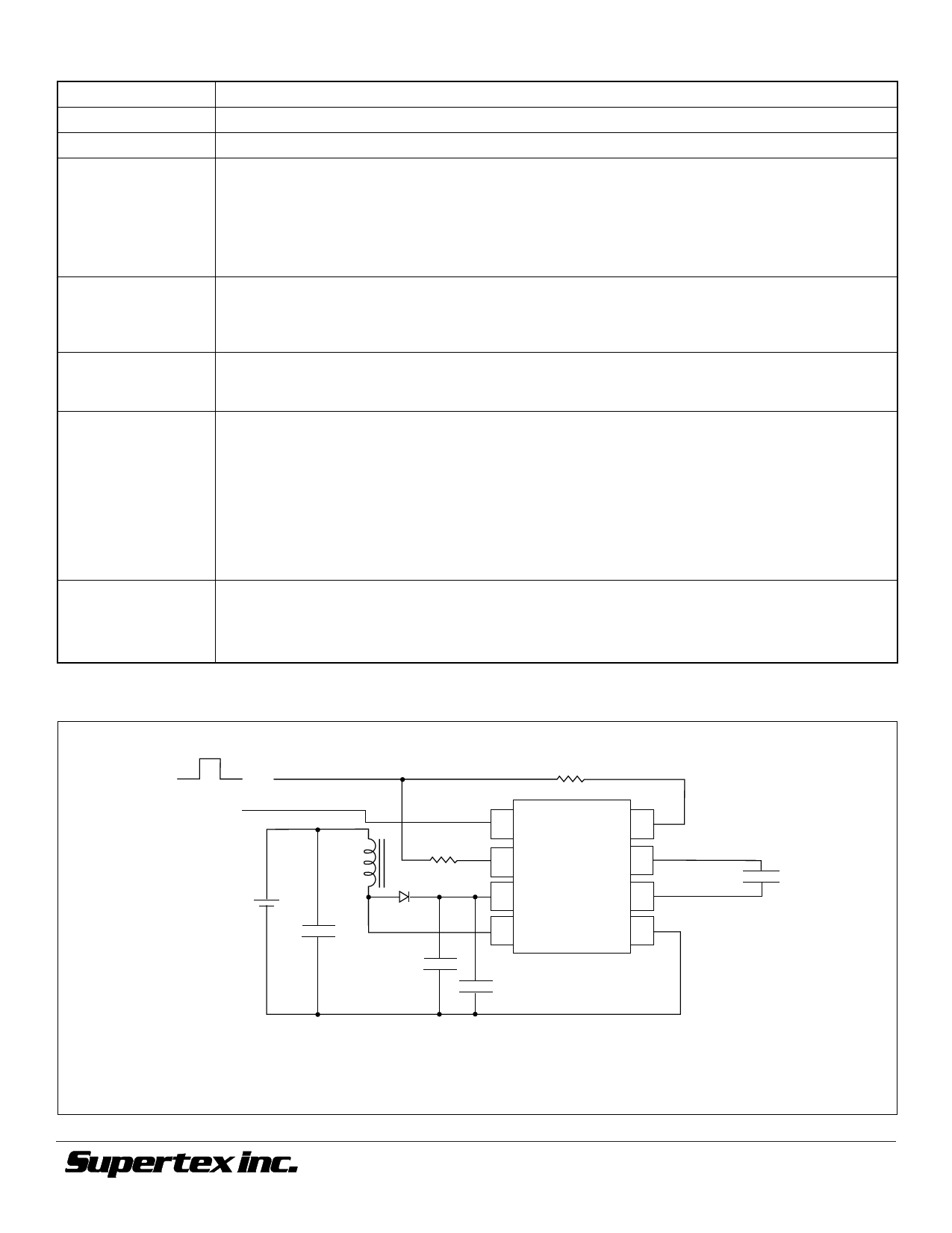
Figure 3: Split Supply Configuration
ON = VDD
OFF = 0V
VDD = Regulated
Voltage
+
VIN = Battery
Voltage –
Remote
Enable
REL
RSW
Lx
BAS21LT1
0.1µF*
CS
200V
1 VDD REL-osc 8
2 RSW-osc
VA 7
3 Cs
VB 6
4 Lx
GND 5
HV830LG
1nF
EL Lamp
*Larger values may be required depending upon supply impedance.
For additional information, see Application Notes AN-H33 and AN-H34.
©2001 Supertex Inc. All rights reserved. Unauthorized use or reproduction prohibited.
4
11/12/01
1235 Bordeaux Drive, Sunnyvale, CA 94089
TEL: (408) 744-0100 • FAX: (408) 222-4895
www.supertex.com
Share Link: 