HV830LG Ver la hoja de datos (PDF) - Supertex Inc
Número de pieza
componentes Descripción
Fabricante
HV830LG Datasheet PDF : 4 Pages
| |||
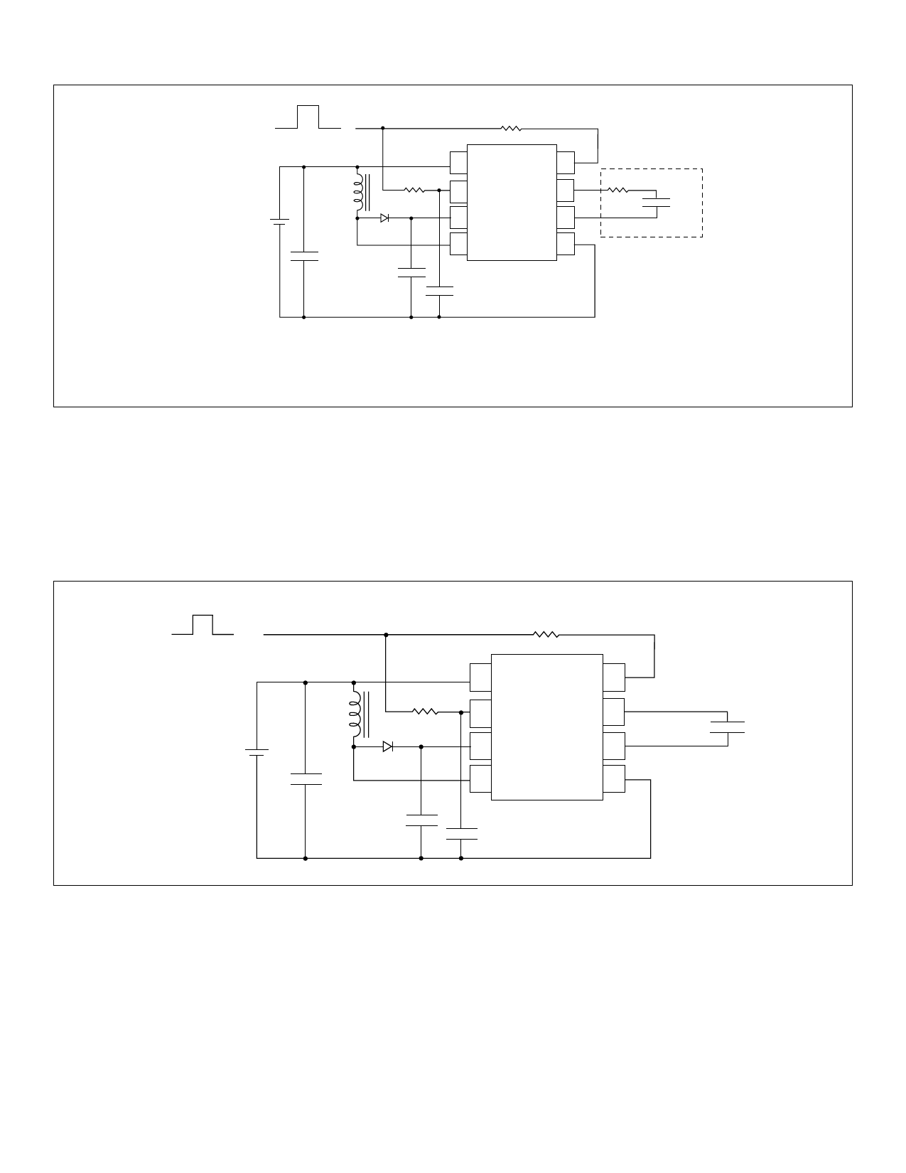
Figure 1: Test Circuit, VIN = 3.0V
ON = VDD
OFF = 0V
5.1MΩ
VDD = VIN = 3.0V
220µH1
1MΩ
BAS21LT1
0.1µF2
0.01µF
200V
1 VDD REL-osc 8
2 RSW-osc
VA 7
3 Cs
VB 6
4 Lx
GND 5
HV830
1nF
10 square inch lamp.
Notes:
1. Murata part # LQH4N221K04 (DC resistance < 5.4Ω)
2. Larger values may be required depending upon supply impedance.
For additional information, see Application Notes AN-H33 and AN-H34.
HV830
Enable/Disable Configuration
The HV830 can be easily enabled and disabled via a logic control
signal on the RSW and REL resistors as shown in Figure 2 below.
The control signal can be from a microprocessor. RSW and REL
are typically very high values. Therefore, only 10’s of microam-
peres will be drawn from the logic signal when it is at a logic high
(enable) state. When the microprocessor signal is high the
device is enabled and when the signal is low, it is disabled.
Figure 2: Enable/Disable Configuration
ON =VDD
OFF = 0V
Remote
Enable
REL
+
VIN = VDD
-
RSW
Lx
BAS21LT1
4.7µF
15V
CS
200V
1 VDD REL-osc 8
2 RSW-osc
VA 7
3 Cs
VB 6
4 Lx
GND 5
HV830LG
1nF
EL Lamp
Split Supply Configuration Using a Single
Cell (1.5V) Battery
The HV830 can also be used for handheld devices operating
from a single cell 1.5V battery where a regulated voltage is
available. This is shown in Figure 3. The regulated voltage can
be used to run the internal logic of the HV830. The amount of
current necessary to run the internal logic is typically 100µA
at a VDD of 3.0V. Therefore, the regulated voltage could easily
provide the current without being loaded down. The HV830
used in this configuration can also be enabled/disabled via
logic control signal on the RSW and REL resistors as shown in
Figure 2.
Split Supply Configuration for Battery
Voltages of Higher than 9.5V
Figure 3 can also be used with high battery voltages such as 12V
as long as the input voltage, VDD, to the HV830 device is within
its specifications of 2.0V to 9.5V.
3
Share Link: 