HAL710SF-K Ver la hoja de datos (PDF) - Unspecified
Número de pieza
componentes Descripción
Fabricante
HAL710SF-K Datasheet PDF : 12 Pages
| |||
HAL710
ADVANCE INFORMATION
1.3. Marking Code
All Hall sensors have a marking on the package sur-
face (branded side). This marking includes the name
of the sensor and the temperature range.
Type
HAL 710
Temperature Range
K
E
710K
710E
1.6. Solderability
All packages: according to IEC68-2-58
During soldering, reflow processing and manual
reworking, a component body temperature of 260 °C
should not be exceeded.
Components stored in the original packaging should
provide a shelf life of at least 12 months, starting from
the date code printed on the labels, even in environ-
ments as extreme as 40 °C and 90% relative humidity.
1.3.1. Special Marking of Prototype Parts
Prototype parts are coded with an underscore beneath
the temperature range letter on each IC. They may be
used for lab experiments and design-ins but are not
intended to be used for qualification test or as produc-
tion parts.
1.4. Operating Junction Temperature Range
The Hall sensors from Micronas are specified to the
chip temperature (junction temperature TJ).
K: TJ = −40 °C to +140 °C
E: TJ = −40 °C to +100 °C
The relationship between ambient temperature (TA)
and junction temperature is explained in Section 4.1.
on page 11.
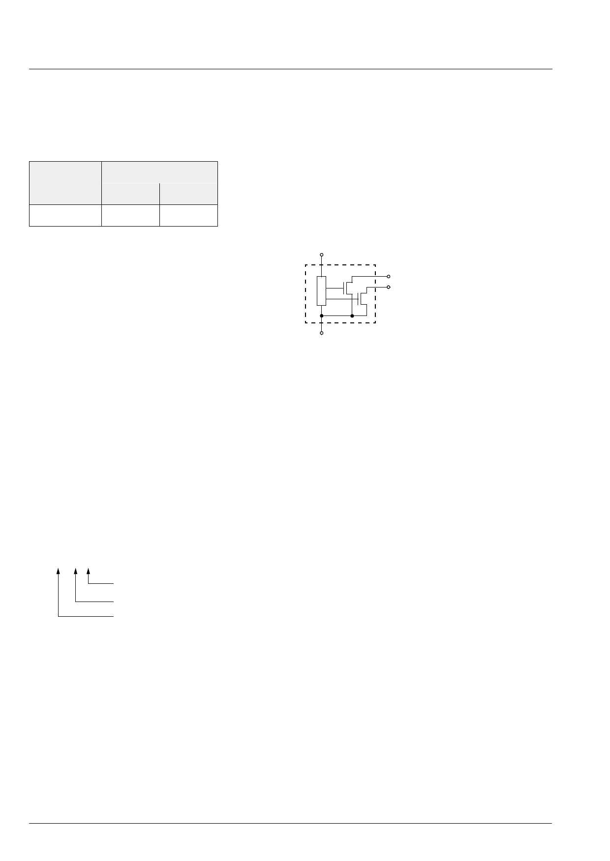
1 VDD
3 Count Output
2 Direction Output
4 GND
Fig. 1–1: Pin configuration
1.5. Hall Sensor Package Codes
HALXXXPA-T
Temperature Range: K, or E
Package: SF for SOT-89B
Type: 710
Example: HAL 710SF-K
→ Type: 710
→ Package: SOT-89B
→ Temperature Range: TJ = −40 °C to +140 °C
Hall sensors are available in a wide variety of packag-
ing quantities. For more detailed information, please
refer to the brochure: “Ordering Codes for Hall Sen-
sors”.
4
Micronas
Share Link: 