KSZ9031MNX Ver la hoja de datos (PDF) - Microsemi Corporation
Número de pieza
componentes Descripción
Fabricante
KSZ9031MNX Datasheet PDF : 73 Pages
| |||
KSZ9031MNX
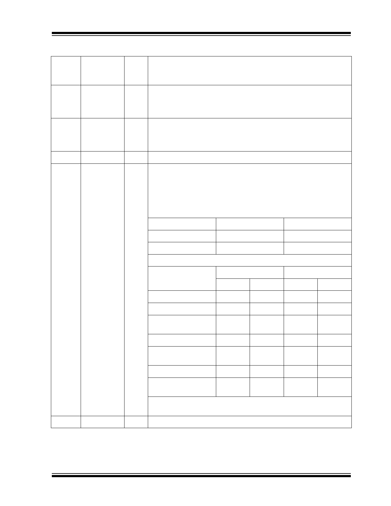
TABLE 2-1: SIGNALS - KSZ9031MNX (CONTINUED)
Pin
Number
Pin
Name
14
TXRXP_D
15
TXRXM_D
16
AVDDH
17
LED2/
PHYAD1
18
DVDDH
Type
Note
2-1
I/O
I/O
P
I/O
P
Description
Media Dependent Interface[3], positive signal of differential pair
1000BASE-T mode: TXRXP_D corresponds to BI_DD+ for MDI configuration
and BI_DC+ for MDI-X configuration, respectively.
10BASE-T/100BASE-TX mode: TXRXP_D is not used.
Media Dependent Interface[3], negative signal of differential pair
1000BASE-T mode: TXRXM_D corresponds to BI_DD– for MDI configuration
and BI_DC– for MDI-X configuration, respectively.
10BASE-T/100BASE-TX mode: TXRXM_D is not used.
3.3V/2.5V (commercial temperature only) analog VDD
LED2 output: Programmable LED2 output
Config mode: The voltage on this pin is sampled and latched during the
power-up/reset process to determine the value of PHYAD[1]. See the Strap-
ping Options - KSZ9031MNX section for details.
The LED2 pin is programmed by the LED_MODE strapping option (Pin 55),
and is defined as follows:
Single-LED Mode
Link
Link Off
Pin State
H
LED Definition
OFF
Link On (any speed)
L
ON
Tri-Color Dual-LED Mode
Link/Activity
Link Off
Pin State
LED2
H
LED1
H
LED Definition
LED2
OFF
LED1
OFF
1000 Link/No Activity
L
H
ON
OFF
1000 Link/Activity
(RX, TX)
Toggle
H
Blinking
OFF
100 Link/No Activity
H
L
OFF
ON
100 Link/Activity
(RX, TX)
10 Link/No Activity
H
Toggle
OFF
Blinking
L
L
ON
ON
10 Link/Activity
(RX, TX)
Toggle
Toggle
Blinking Blinking
For tri-color dual-LED mode, LED2 works in conjunction with LED1 (Pin 19) to
indicate 10 Mbps link and activity.
3.3V, 2.5V, or 1.8V digital VDD_IO
2016 Microchip Technology Inc.
DS00002096C-page 7
Share Link: 