FAN3988 Ver la hoja de datos (PDF) - ON Semiconductor
Número de pieza
componentes Descripción
Fabricante
FAN3988 Datasheet PDF : 8 Pages
| |||
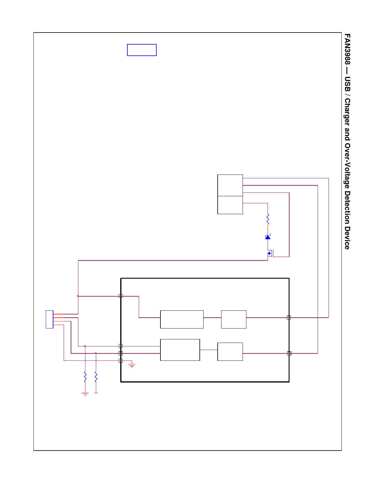
Without USB Transceiver (Figure 8)
The FAN3988 sets the FLAG1 pin to logic HIGH or
LOW as an indicator to the system controller that a
standard USB device or a charger is connected to the
USB port. The FAN3988 also monitors the VBUS for
over- or under-voltage conditions. The FLAG2 pin is set
LOW if VBUS is less than 3.3 V or greater than 6.0 V.
In a condition where a USB transceiver is not
incorporated or there is a switch between the USB port
and the FAN3988, external resistors must be used to
set the correct input logic states on the D+ D- inputs. A
5 MΩ pull-down on the D- line and a 1 MΩ pull-up to
VDD (system supply) on the D+ line are recommended.
When a condition exists where a charger is plugged into
the USB port (D+ D- shorted), the voltage divider of
1 MΩ and 5 MΩ puts a voltage of 2.75 V on the D+ D-
inputs and flag1 is HIGH, indicating a charger is
connected to port.
In a condition where the USB port is connected to a
standard USB device, the D+ input is pulled up to VDD
(system supply) in parallel with the 1.5 kΩ on a USB
transceiver with a parallel R value of 1.497 kΩ. The D-
input is connected to a 15 kΩ pull-down by the USB
device and in parallel with 5 MΩ with a parallel R value
of 14.955 kΩ. This condition makes flag1 LOW.
If D+ and D- are open (floating), D+ is pulled to VDD
(system supply) and D- floats LOW, which makes
flag1 LOW.
Control
Battery
Rsense
Vbus
D-
D+
Gnd
USB
Vbus
Comparator
OVP
UVP
Logic
D-
D+
GND
5M 1M
Std USB/
Charger
Detect
Logic
Vdd
Figure 8. Typical System Application without USB Transceiver
Flag 2
Flag 1
www.onsemi.com
7
Share Link: 