A3953 Ver la hoja de datos (PDF) - Allegro MicroSystems
Número de pieza
componentes Descripción
Fabricante
A3953 Datasheet PDF : 14 Pages
| |||
3953
FULL-BRIDGE
PWM MOTOR DRIVER
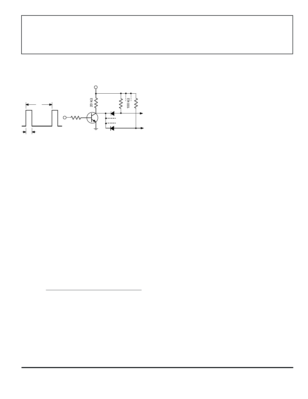
Figure 3
Synchronous Fixed-Frequency Control Circuit
V CC
t2
RC1
1N4001
2N2222
t
1
RC N
Dwg. EP-060
Miscellaneous Information. A logic high applied to both
the ENABLE and MODE terminals puts the device into a
sleep mode to minimize current consumption when not in
use.
An internally generated dead time prevents crossover
currents that can occur when switching phase or braking.
Thermal protection circuitry turns off all drivers should
the junction temperature reach 165°C (typical). This is
intended only to protect the device from failures due to
excessive junction temperatures and should not imply that
output short circuits are permitted. The hysteresis of the
thermal shutdown circuit is approximately 15°C.
APPLICATION NOTES
Current Sensing. The actual peak load current (IPEAK)
will be above the calculated value of ITRIP due to delays in
the turn off of the drivers. The amount of overshoot can
be approximated by:
(VBB – [(ITRIP x RLOAD) + VBEMF]) x tPWM(OFF)
IOS ≈
LLOAD
where VBB is the motor supply voltage, VBEMF is the back-
EMF voltage of the load, RLOAD and LLOAD are the resis-
tance and inductance of the load respectively, and
tPWM(OFF) is specified in the electrical characteristics table.
The reference terminal has a maximum input bias
current of ±5 µA. This current should be taken into
account when determining the impedance of the external
circuit that sets the reference voltage value.
To minimize current-sensing inaccuracies caused by
ground trace I x R drops, the current-sensing resistor
should have a separate return to the ground terminal of
the device. For low-value sense resistors, the I x R drops
in the printed wiring board can be significant and should
be taken into account. The use of sockets should be
avoided as their contact resistance can cause variations in
the effective value of RS.
Generally, larger values of RS reduce the aforemen-
tioned effects but can result in excessive heating and
power loss in the sense resistor. The selected value of RS
should not cause the absolute maximum voltage rating of
1.0 V (0.4 V for VCC = 3.3 V operation), for the SENSE
terminal, to be exceeded.
The current-sensing comparator functions down to
ground allowing the device to be used in microstepping,
sinusoidal, and other varying current-profile applications.
Thermal Considerations. For reliable operation it is
recommended that the maximum junction temperature be
kept below 110°C to 125°C. The junction temperature can
be measured best by attaching a thermocouple to the
power tab/batwing of the device and measuring the tab
temperature, TTAB. The junction temperature can then be
approximated by using the formula:
TJ ≈ TTAB + (ILOAD x 2 x VF x RθJT)
where VF may be chosen from the electrical specification
table for the given level of ILOAD. The value for RθJT is
given in the package thermal resistance table for the
appropriate package.
The power dissipation of the batwing packages can be
improved by 20% to 30% by adding a section of printed
circuit board copper (typically 6 to 18 square centimeters)
connected to the batwing terminals of the device.
The thermal performance in applications that run at
high load currents and/or high duty cycles can be im-
proved by adding external diodes in parallel with the
internal diodes. In internal PWM slow-decay applications,
only the two ground clamp diodes need be added. For
internal fast-decay PWM, or external PHASE or ENABLE
input PWM applications, all four external diodes should be
added for maximum junction temperature reduction.
PCB Layout. The load supply terminal, VBB, should be
decoupled with an electrolytic capacitor (>47 µF is recom-
www.allegromicro.com
9
Share Link: 