A3953 Ver la hoja de datos (PDF) - Allegro MicroSystems
Número de pieza
componentes Descripción
Fabricante
A3953 Datasheet PDF : 14 Pages
| |||
3953
FULL-BRIDGE
PWM MOTOR DRIVER
FUNCTIONAL DESCRIPTION
Internal PWM Current Control During Forward and
Reverse Operation. The A3953S— contains a fixed off-
time pulse-width modulated (PWM) current-control circuit
that can be used to limit the load current to a desired
value. The peak value of the current limiting (ITRIP) is set
by the selection of an external current sensing resistor
(RS) and reference input voltage (VREF). The internal
circuitry compares the voltage across the external sense
resistor to the voltage on the reference input terminal
(REF) resulting in a transconductance function approxi-
mated by:
ITRIP ≈
VREF
RS
– ISO
where ISO is the offset due to base drive current.
In forward or reverse mode the current-control cir-
cuitry limits the load current as follows: when the load
current reaches ITRIP, the comparator resets a latch that
turns off the selected source driver or selected sink and
source driver pair depending on whether the device is
operating in slow or fast current-decay mode, respec-
tively.
In slow current-decay mode, the selected source
driver is disabled; the load inductance causes the current
to recirculate through the sink driver and ground clamp
diode. In fast current-decay mode, the selected sink and
source driver pair are disabled; the load inductance
causes the current to flow from ground to the load supply
via the ground clamp and flyback diodes.
Figure 1 — Load-Current Paths
V
BB
DRIVE CURRENT
RECIRCULATION (SLOW-DECAY MODE)
RECIRCULATION (FAST-DECAY MODE)
RS
Dwg. EP-006-13A
The user selects an external resistor (RT) and capaci-
tor (CT) to determine the time period (tOFF = RT x CT)
during which the drivers remain disabled (see “RC Fixed
Off-Time” below). At the end of the RC interval, the
drivers are enabled allowing the load current to increase
again. The PWM cycle repeats, maintaining the peak
load current at the desired value (see figure 2).
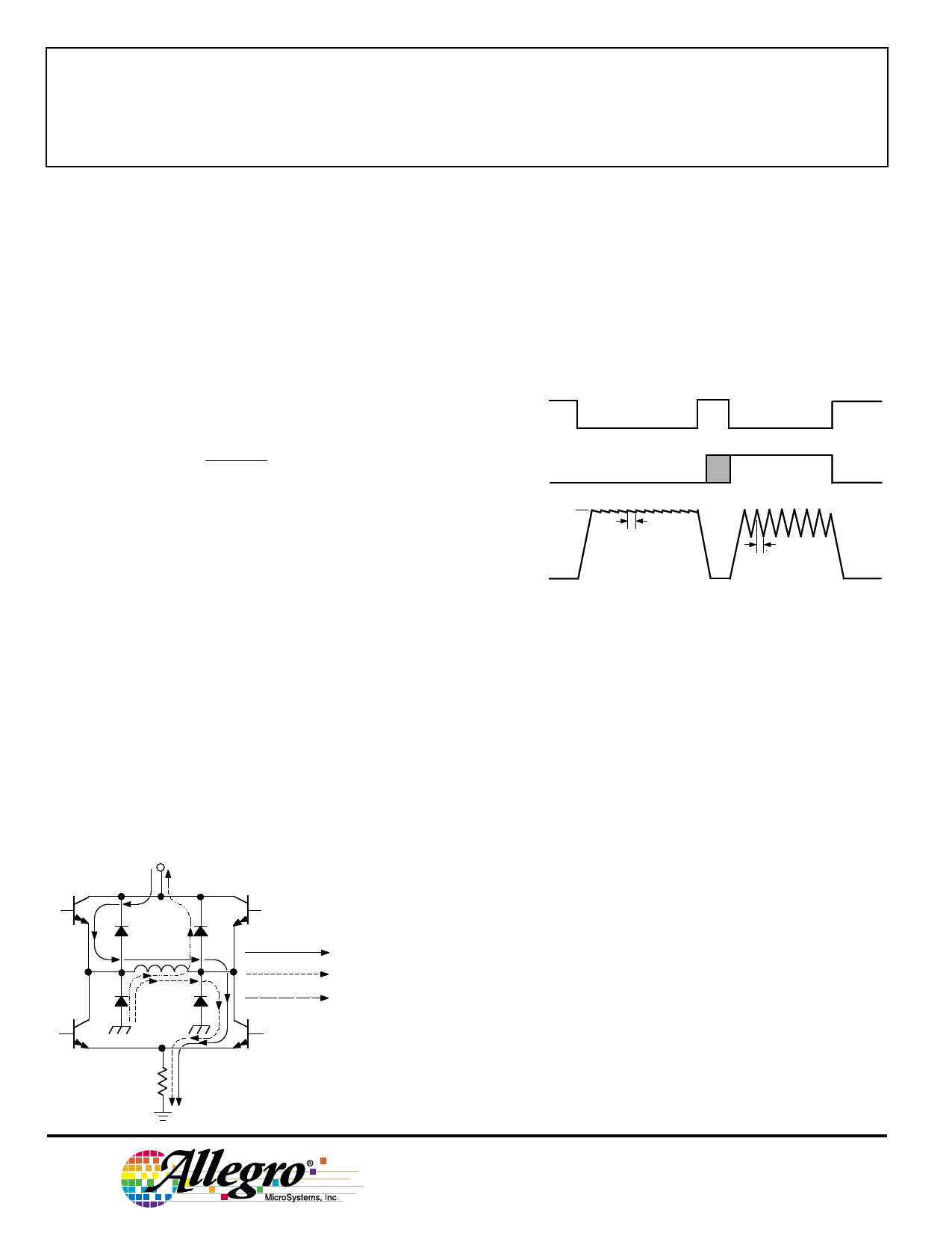
Figure 2
Fast and Slow Current-Decay Waveforms
ENABLE
MODE
I TRIP
RC
LOAD
CURRENT
RC
Dwg. WP-015-1
INTERNAL PWM CURRENT CONTROL
DURING BRAKE-MODE OPERATION
Brake Operation - MODE Input High. The brake circuit
turns off both source drivers and turns on both sink
drivers. For dc motor applications, this has the effect of
shorting the motor’s back-EMF voltage resulting in current
flow that dynamically brakes the motor. If the back-EMF
voltage is large, and there is no PWM current limiting, the
load current can increase to a value that approaches that
of a locked rotor condition. To limit the current, when the
ITRIP level is reached, the PWM circuit disables the
conducting sink drivers. The energy stored in the motor’s
inductance is discharged into the load supply causing the
motor current to decay.
As in the case of forward/reverse operation, the
drivers are enabled after a time given by tOFF = RT x CT
(see “RC Fixed Off-Time” below). Depending on the
back-EMF voltage (proportional to the motor’s decreasing
speed), the load current again may increase to ITRIP. If so,
the PWM cycle will repeat, limiting the peak load current
to the desired value.
115 Northeast Cutoff, Box 15036
6
Worcester, Massachusetts 01615-0036 (508) 853-5000
Share Link: 