ST75185C Ver la hoja de datos (PDF) - STMicroelectronics
Número de pieza
componentes Descripción
Fabricante
ST75185C Datasheet PDF : 22 Pages
| |||
ST75185C
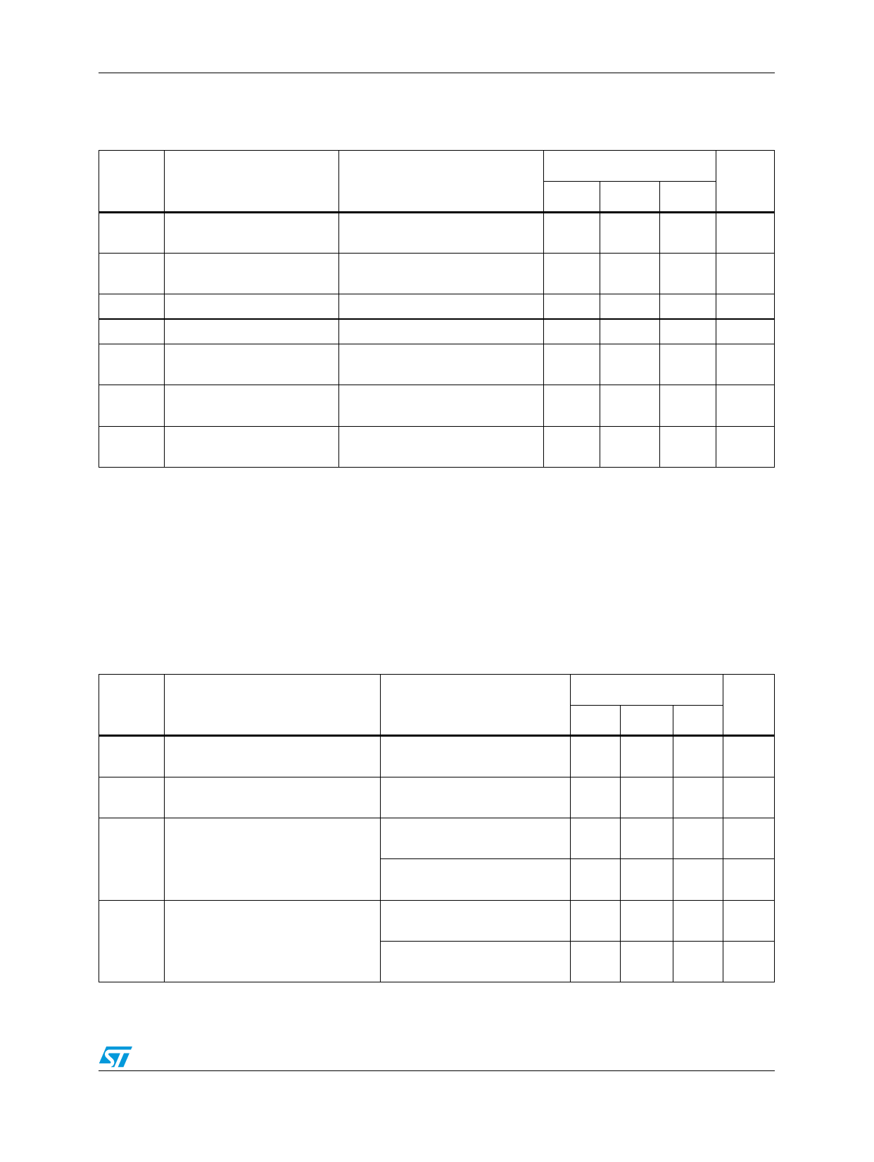
Electrical characteristics
VDD = 9 V, VSS = -9 V, VCC = 5 V, unless otherwise specified.
Table 8. Driver electrical characteristics over operating free-air temperature range
Symbol
Parameter
Test conditions
Value
Unit
Min. Typ. Max.
VOH
VOL
IIH
IIL
IOS(H)
IOS(L)
RO
High level output voltage
VIL = 0.8 V, RL = 3kΩ
(See Figure 3)
Low level output voltage
(Note 3)
VIH = 1.9 V, RL = 3kΩ
(See Figure 3)
High level input current
Low level input current
High level short circuit
output current (Note 4)
VI = 5 V (See Figure 4)
VI = 0 V (See Figure 4)
VIL = 0.8 V, VO = 0 V
(See Figure 3)
Low level short circuit output VIH = 2 V VO = 0 V
current
(See Figure 3)
Output resistance
VDD = VSS = VCC = 0 V
VO = -2 to 2 V (Note 3)
6
7.5
V
-7.5
-6
V
10
µA
−1.6
mA
-4.5
−12 −19.5 mA
4.5
12
19.5
mA
300
Ω
Note: 1 The algebraic convention, where the more positive (less negative) limits designated as
maximum, is used in this datasheet for logic levels only (e.g. if - 10 V is a maximum, the
typical value is a more negative voltage).
2 Output short circuit conditions must maintain the total power dissipation below absolute
maximum ratings.
3 Test conditions are those specified by EIA-232-E and as listed above.
VDD = 12 V, VSS = -12 V, VCC = 5 V, TA = 25 °C
Table 9. Driver switching characteristics
Symbol
Parameter
Test conditions
Value
Unit
Min. Typ. Max.
tPLH
Propagation Delay Time, Low to
High Level Output
RL = 3 to 7 kΩ CL = 15 pF
(See Figure 5, Figure 6)
tPHL
Propagation Delay Time, High to
Low Level Output
RL = 3 to 7 kΩ CL = 15 pF
(See Figure 5, Figure 6)
RL = 3 to 7 kΩ CL = 15 pF
tTLH
Transition Time Low to High Level (See Figure 5, Figure 6)
Output
RL = 3 to 7 kΩ CL = 2500 pF
(Note 4, Figure 5, Figure 6)
RL = 3 to 7 kΩ CL = 15 pF
tTHL
Transition Time High to Low Level (See Figure 5, Figure 6)
Output
RL = 3 to 7 kΩ CL = 2500 pF
(Note 4, Figure 5, Figure 6)
315 500 ns
75 175 ns
60 100 ns
1.7
2.5
µs
40
7.5
ns
1.5
2.5
µs
4 Measured between -3 V and 3 V points of output waveform (EIA-232-E conditions), all
unused inputs are tied.
Doc ID 6228 Rev 18
7/22
Share Link: 