OM9369CM Ver la hoja de datos (PDF) - Omnirel Corp => IRF
Número de pieza
componentes Descripción
Fabricante
OM9369CM
Omnirel Corp => IRF

OM9369CM Datasheet PDF : 10 Pages
| |||
OM9369CM
APPLICATIONS
Modes of Operation
Figures 2 and 3, shown on the following pages,
provide schematic representations of typical voltage-
mode and current-mode applications for the
OM9369CM controller/driver.
Figure 2 represents the implementation of a typical
voltage-mode controller for velocity control. A voltage
or speed command is applied to the non-inverting
input of the error amplifier which is configured as a
voltage follower. The output of the error amplifier is
compared to a pulse width modulated ramp, and since
motor speed is nearly proportional to the average
phase output voltage, the speed is controlled via duty
cycle control. If a speed feedback loop is required, the
tachometer output can be connected to the inverting
input of the error amplifier via a loop compensation
network.
Figure 2 also shows the implementation of the cycle-
by-cycle current limit/overcurrent protection feature of
the OM9369CM. The load current is monitored via the
controller’s internal sense resistor. The current sense
signal is filtered and fed into the current sense
amplifier where the absolute value of ISH-ISL is
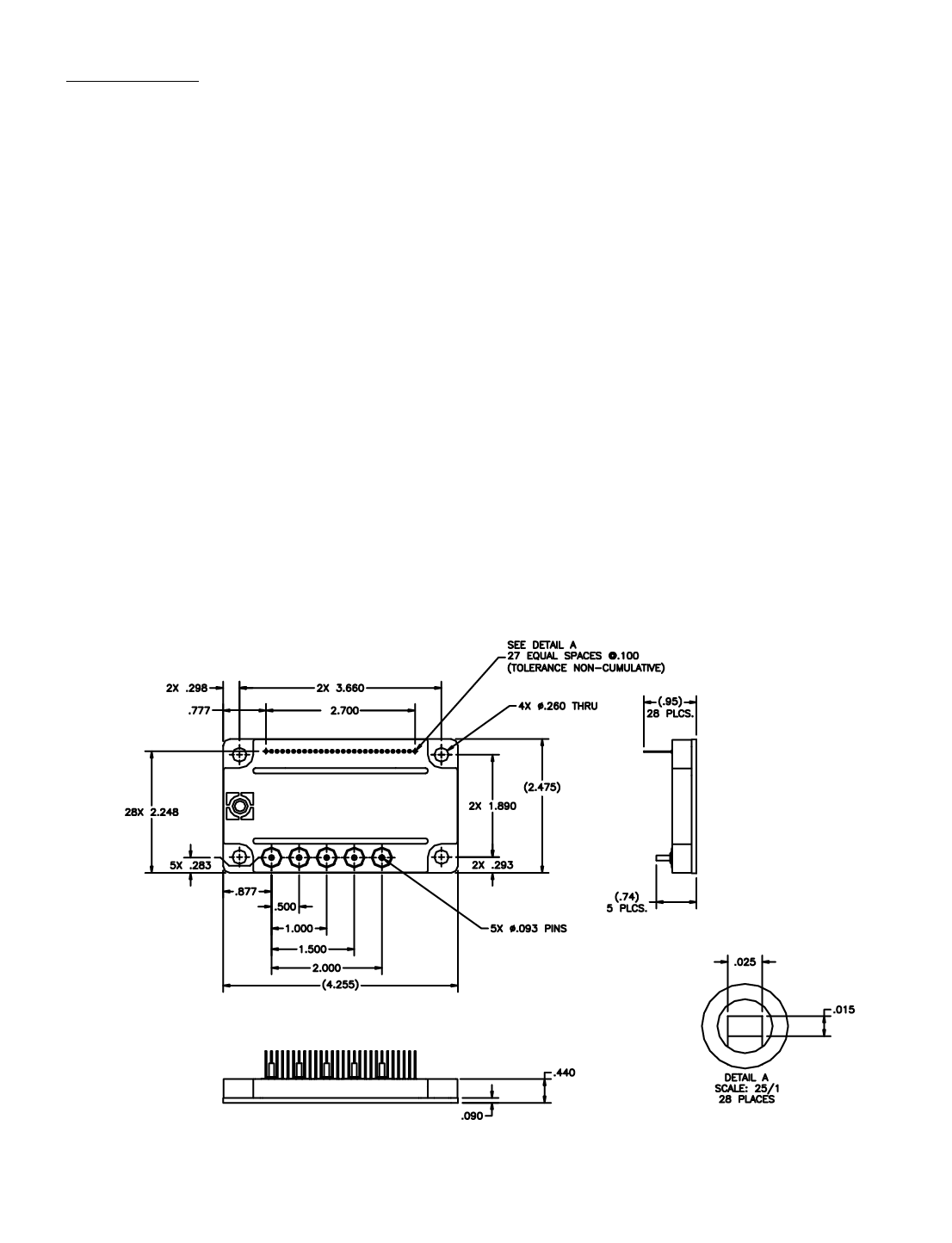
MECHANICAL OUTLINE
multiplied by two and biased up by 2.5 volts.
The output of the current sense amplifier is compared
to a fixed reference, thus providing cycle-by-cycle
current limiting and/or overcurrent protection as
necessary. The typical peak current threshold (ISH-
ISL) is 0.20 volts; the typical over current threshold
(ISH-ISL) is 0.30 volts.
Figure 3 represents the implementation of a typical
current-mode controller for torque control. The load
current is monitored via the controller’s internal sense
resistor. The current sense signal is filtered and fed
into the current sense amplifier where the absolute
value of ISH-ISL is multiplied by two and biased up by
2.5 volts. Besides the implementation of the cycle-by-
cycle current limit/overcurrent protection feature of the
OM9369CM discussed in the preceding paragraph, the
output of the current sense amplifier is fed into the error
amplifier which is configured as a differential amplifier.
An error signal representing the difference between the
current command input and the value of the amplified
current sense signal is produced. Then it is compared
to a pulse width modulated ramp and since torque is
nearly proportional to the average phase output
current, the torque is controlled via duty cycle control.
Fig 1: Mechanical Outline CM-1LP CERMOD TM
2.1 - 9
Share Link: