TDA2030A Ver la hoja de datos (PDF) - Unisonic Technologies
Número de pieza
componentes Descripción
Fabricante
TDA2030A Datasheet PDF : 14 Pages
| |||
TDA2030A
LINEAR INTEGRATED CIRCUIT
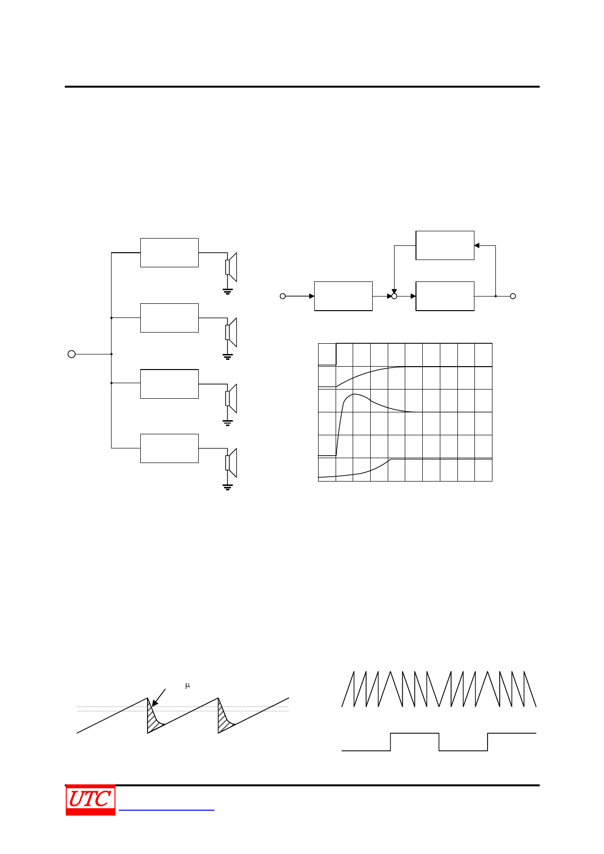
TRANSIENT INTER-MODULATION DISTORTION(TIM)
Transient inter-modulation distortion is an unfortunate phenomena associated with negative-feedback amplifiers.
When a feedback amplifier receives an input signal which rises very steeply, i.e. contains high-frequency
components, the feedback can arrive too late so that the amplifiers overloads and a burst of inter-modulation
distortion will be produced as in Fig.5. Since transients occur frequently in music this obviously a problem for the
designed of audio amplifiers. Unfortunately, heavy negative feedback is frequency used to reduce the total harmonic
distortion of an amplifier, which tends to aggravate the transient inter-modulation (TIM situation.)
Fig.4 High Power Active Box For Musical Instrument
20 to 40W
Amplifier
20 to 40W
Amplifier
Fig.5 Overshoot Phenomenon In Feedback Amplifiers
FEEDBACK
PATH
¦ÂV4
INPUT
PRE AMPLIFIER
V1
V2
V3
POWER
AMPLIFIER
OUTPUT
V4
V1
20 to 40W
V2
Amplifier
20 to 40W
Amplifier
V3
V4
The best known method for the measurement of TIM consists of feeding sine waves superimposed onto square
wavers, into the amplifier under test. The output spectrum is then examined using a spectrum analyzer and
compared to the input. This method suffers from serious disadvantages: the accuracy is limited, the measurement is
a tatter delicate operation and an expensive spectrum analyzer is essential.
The "inverting-sawtooth" method of measurement is based on the response of an amplifier to a 20KHz saw-tooth
wave-form. The amplifier has no difficulty following the slow ramp but it cannot follow the fast edge. The output will
follow the upper line in Fig. 6 cutting of the shade area and thus increasing the mean level. If this output signal is
filtered to remove the saw-tooth, direct voltage remains which indicates the amount of TIM distortion, although it is
difficult to measure because it is indistinguishable from the DC offset of the amplifier. This problem is neatly avoided
in the IS-TIM method by periodically inverting the saw-tooth wave-form at a low audio frequency as shown in Fig.7.In
the case of the saw-tooth in Fig. 8 the mean level was increased by the TIM distortion, for a saw-tooth in the other
direction the opposite is true.
SR(V/ s)
m2
m1
Fig.6 20kHz Sawtooth Waveform
UNISONIC TECHNOLOGIES CO., LTD
www.unisonic.com.tw
Input
Signal
Filtered
Output
Siganal
Fig. 7 Inverting Sawtooth Waveform
11 of 14
QW-R107-005,C
Share Link: 