7672(2001) Ver la hoja de datos (PDF) - MAXWELL TECHNOLOGIES
Número de pieza
componentes Descripción
Fabricante
7672 Datasheet PDF : 11 Pages
| |||
12-Bit A/D Converter
7672
PARAMETER
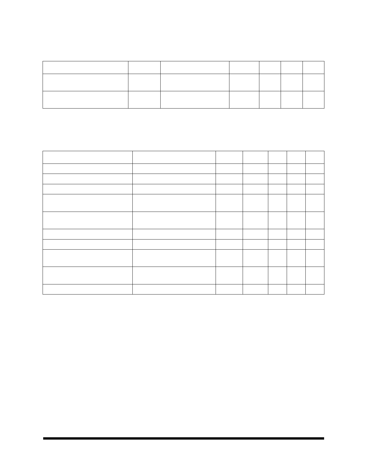
TABLE 4. 7672 DC ELECTRICAL CHARACTERISTICS
(VDD = 5V ±5%, VSS = -12V ±10%, VREF = -5V, TA = -55 TO 125 °C UNLESS OTHERWISE SPECIFIED)
SYMBOL TEST CONDITION
MIN
MAX
Bipolar Zero Error
Bipolar Gain Error
1. Guaranteed by design.
BZE TA = +25°C
TA = -55 to +125°C
BGE TA = +25°C
TA = -55 to +125°C
--
±5
--
±6
--
±5
--
±7
UNITS
LSB
LSB
PARAMETER
TABLE 5. 7672 TIMING CHARACTERISTICS 1,2
(VDD = 5V ±5%, VSS = -12V ±10%, VREF = -5V, TA = -55 TO 125 °C UNLESS OTHERWISE SPECIFIED)
TEST CONDITION
SYMBOL
MIN
MAX
UNITS
Conversion Time, Synchronous Clk, 3 12.5 clks, TA = -55 to +125 °C
tCONV
--
5.0
us
--
10
Conversion Time, Asynchronous Clk, 12-13 clks, TA = -55 to +125 °C
tCONV
4.8
5.2
us
9.6
10.4
CS to RD Setup Time
RD to BUSY Delay
Data Access Time 4
RD Pulse Width
CS to RD Hold Time
Data Setup Time After BUSY4
Bus Relinguish Time5
Delay Between Read Operations
TA = -55 to +125 °C
CL = 50 pF, TA = +25 °C
CL = 50 pF, TA = -55 to +125 °C
CL = 100 pF, TA = +25 °C
CL = 100 pF, TA = -55 to +125 °C
TA = -55 to +125 °C
TA = -55 to +125 °C
CL = 100 pF, TA = +25 °C
CL = 100 pF, TA = -55 to +125 °C
(TA = +25 °C)
(-55 < TA < +125 °C)
(-55 < TA < +125 °C)
t1
0
--
ns
t2
--
190
ns
--
270
t3
--
125
ns
--
170
t4
t3
--
ns
t5
0
--
ns
t6
--
70
ns
--
--
100
t7
--
75
ns
--
90
t8
200
--
ns
1. 1LSB = FS/4096; TA = 25 °C; Performance over power supply tolerance is guaranteed by power supply rejection test.
2. All inputs are 0V to +5V swing with tr = tr = 5ns (10 to 90% of +5V) and timed from a voltage level of +1.6V.
3. Functionally tested.
4. t3 and t6 are measured with the load circuits of Figure 1 and are defined as the time required for an output to cross +0.8 or
+2.4.
5. t7 is defined as the time required for the data lines to change 0.5V when loaded with the circuit of Figure 2.
1000565
12.19.01 Rev 11
All data sheets are subject to change without notice 4
©2001 Maxwell Technologies
All rights reserved.
Share Link: 