MUR120 Ver la hoja de datos (PDF) - DIYI Electronic Technology Co., Ltd.
Número de pieza
componentes Descripción
Fabricante
MUR120 Datasheet PDF : 2 Pages
| |||
MUR120 THRU MUR1100
1.0 AMP Silicon Ultra Fast Rectifiers
Features
· Low power loss.
· High current capability
· High reliability
· High surge current capability
· Plastic material-UL flammability 94V-0
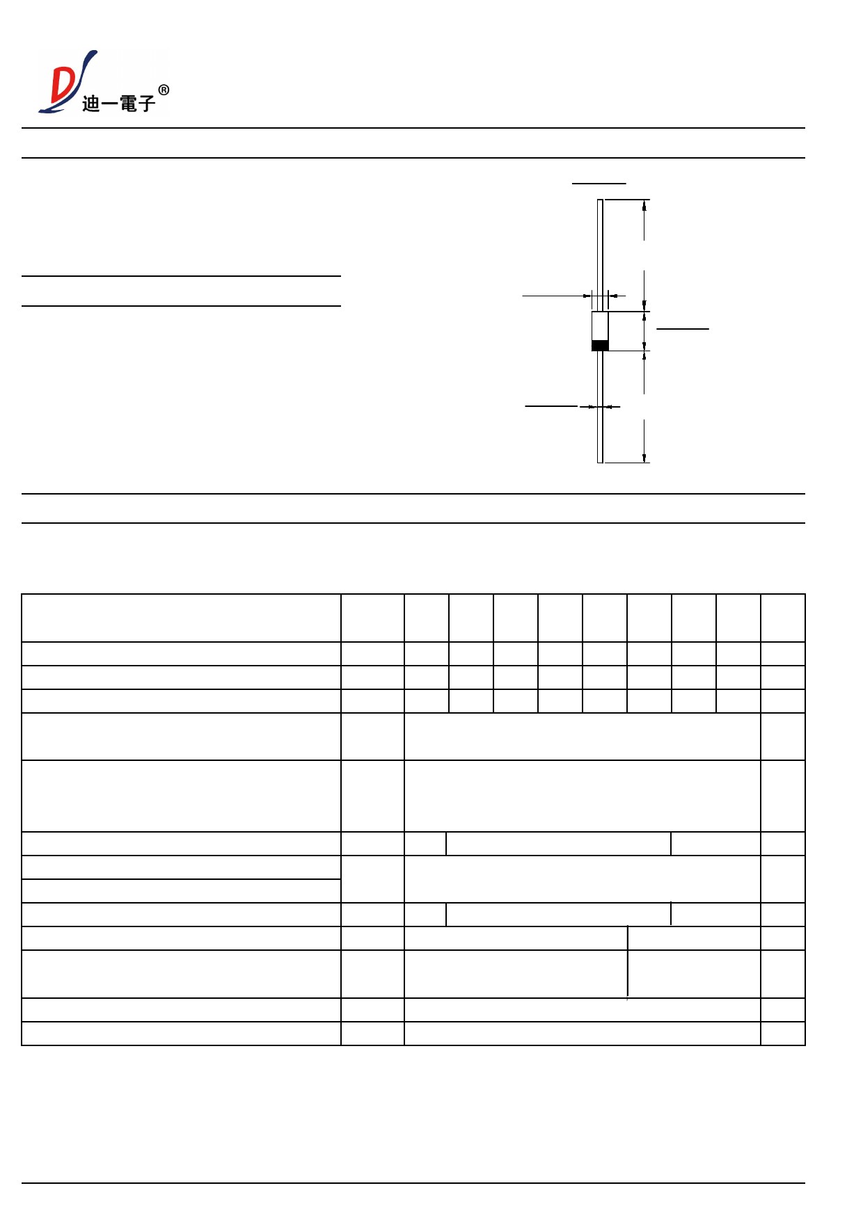
DO-41
˄˅
MIN.
Mechanical Data
· Case: Molded plastic DO-41
· Terminals: Plated leads solderable per
MIL-STD-202,Method 208 guaranteed
· Polarity: Color band dentes cathode end
· Mounting Position: Any
· Making: Type Number
· Lead Free: For RoHS/Lead Free Version
˄˅
DIA.
˄˅
˄˅
MAX
DIA. ˄˅
˄˅
˄˅
MIN.
Dimensions in inches and (millimeters)
Maximum Ratings and Electrical Characteristics
Rating at 25℃ ambient temperature unless otherwise specified
Single phase,half wave,60Hz,resistive or inductive load
For capacitive load derate current by 20%
Type Number
SYMBOL
MUR
120
MUR
130
MUR MUR
140 150
MUR MUR
160 170
MUR MUR
180 1100
Unit
Maximum Recurrent Peak Reverse Voltage
Maximum RMS Voltage
Maximum DC Blocking Voltage
Average Rectified Output Current (Note 1)
@TA =75 ℃
VRRM 200 300 400 500 600 700 800 1000 V
VRMS 140 210 280 350 420 490 560 700 V
VDC 200 300 400 500 600 700 800 1000 V
IO
1.0
A
Peak Forward Surge Current 8.3ms Single half
sine-wave superimposed on rated load (JEDEC IFSM
30
A
Method)
Forward Voltage @IF=1.0A
Peak Reverse Current @TA =25℃
At Rated DC Blocking Voltage @TA =100℃
Maximum Reverse Recovery Time (Note2 )
Typical Junction Capacitance (Note 3)
Typical Thermal Resistance Junction to
Ambient(Note 1)
Operating Temperature Range
Storage Temperature Range
VFM 0.9
IR
TRR
25
CJ
RθJA
TJ
TSTG
1.25
5.0
100
50
22
50
-55 to + 125
-55 to + 150
1.7
75
15
60
V
uA
nS
pF
℃/W
℃
℃
Note: 1. Leads maintained at ambient temperature at a distance of 9.5mm from the case
2. Reverse Recovery Test Conditions: IF=0.5A, IR=1A, Irr=0.25A.
3. Measured at 1.0 MHz and Applied reverse Voltage of 4.0V D.C
version:01
1of2
www.dyelec.com
Share Link: 