TCLT1002(2007) Ver la hoja de datos (PDF) - Vishay Semiconductors
Número de pieza
componentes Descripción
Fabricante
TCLT1002
(Rev.:2007)
(Rev.:2007)
Vishay Semiconductors

TCLT1002 Datasheet PDF : 9 Pages
| |||
TCLT10..Series
Vishay Semiconductors Optocoupler, Phototransistor Output,
SOP-4L, Long Mini-Flat Package
300
250
Phototransistor
Psi (mW)
200
150
100
50
0
0
94 9182
IR-Diode
Isi (mA)
25 50 75 100 125 150
Tsi - Safety Temperature (°C)
Fig. 1 - Derating Diagram
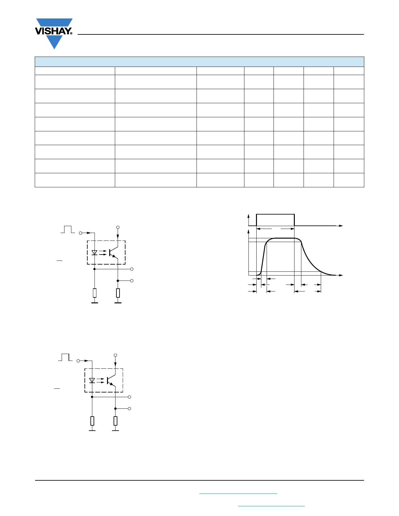
SWITCHING CHARACTERISTICS
PARAMETER
TEST CONDITION
Delay time
VS = 5 V, IC = 2 mA, RL = 100 Ω,
(see figure 3)
Rise time
VS = 5 V, IC = 2 mA, RL = 100 Ω,
(see figure 3)
Fall time
VS = 5 V, IC = 2 mA, RL = 100 Ω,
(see figure 3)
Storage time
VS = 5 V, IC = 2 mA, RL = 100 Ω,
(see figure 3)
Turn-on time
VS = 5 V, IC = 2 mA, RL = 100 Ω,
(see figure 3)
Turn-off time
VS = 5 V, IC = 2 mA, RL = 100 Ω,
(see figure 3)
Turn-on time
VS = 5 V, IF = 10 mA, RL = 1 kΩ,
(see figure 4)
Turn-off time
VS = 5 V, IF = 10 mA, RL = 1 kΩ,
(see figure 4)
VIOTM
VPd
VIOWM
VIORM
t1, t2 = 1 to 10 s
t3, t4 = 1 s
ttest = 10 s
tstres = 12 s
0
13930
t1
tTr = 60 s
t3 ttest t4
t2 t stres
t
Fig. 2 - Test Pulse Diagram for Sample Test according to
DIN EN 60747-5-2 (VDE 0884)/DIN EN 60747-; IEC60747
SYMBOL
td
tr
tf
ts
ton
toff
ton
toff
MIN.
TYP.
3
3
4.7
0.3
6
5
9
10
MAX.
UNIT
µs
µs
µs
µs
µs
µs
µs
µs
IF IF
0
RG = 50
tp = 0.01
T
tp = 50 µs
50
95 10804
+5V
IC = 2 mA; adjusted through
input amplitude
Channel I
Oscilloscope
Channel II
RL = 1 M
CL = 20 pF
100
Fig. 3 - Test Circuit, Non-Saturated Operation
IF IF = 10 mA
0
+5V
IC
RG = 50 Ω
tp = 0.01
T
tp = 50 µs
95 10843
50 Ω
Channel I
1 kΩ
Channel II
Oscilloscope
RL ≥ 1 MΩ
CL ≤ 20 pF
Fig. 4 - Test Circuit, Saturated Operation
www.vishay.com
4
For technical questions, contact: optocoupler.answers@vishay.com
Document Number: 83515
Rev. 2.2, 21-Nov-07
Share Link: