ACPL-054L Ver la hoja de datos (PDF) - Broadcom Corporation
Número de pieza
componentes Descripción
Fabricante
ACPL-054L Datasheet PDF : 18 Pages
| |||
ACPL-M50L, ACPL-054L, ACPL-W50L, ACPL-K54L
Data Sheet
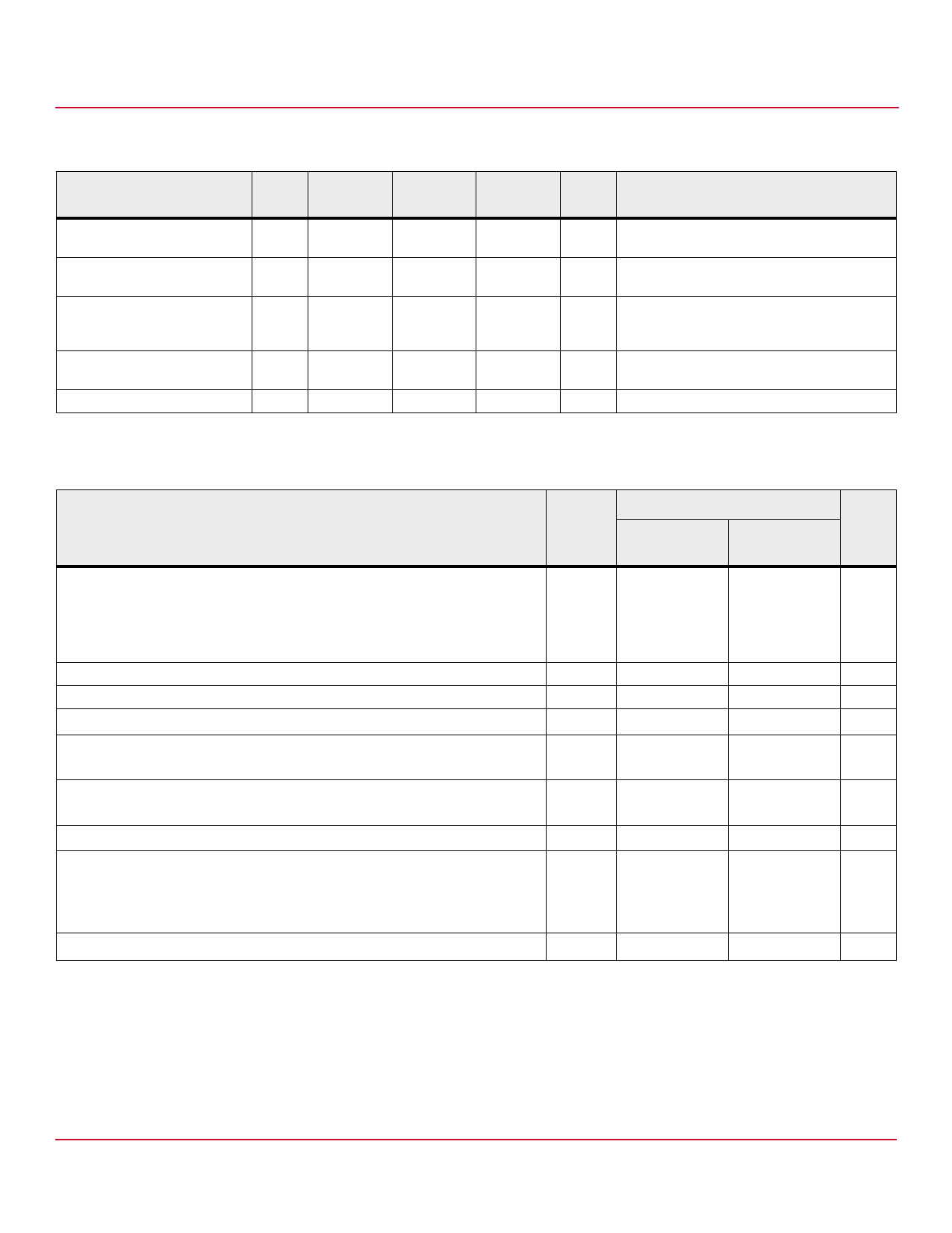
Table 3 Insulation and Safety Related Specifications
Parameter
Symbol ACPL-M50L
ACPL-054L
ACPL-W50L
ACPL-K24L
Units
Conditions
Minimum External Air Gap
L(101)
5
4.9
8
mm Measured from input terminals to output
(Clearance)
terminals, shortest distance through air.
Minimum External Tracking
L(102)
5
4.8
8
mm Measured from input terminals to output
(Creepage)
terminals, shortest distance path along body.
Minimum Internal Plastic Gap
(Internal Clearance)
0.08
0.08
0.08
mm Through insulation distance conductor to
conductor, usually the straight line distance
thickness between the emitter and detector.
Tracking Resistance
CTI
175
175
175
V DIN IEC 112/VDE 0303 Part 1
(Comparative Tracking Index)
Isolation Group
IIIa
IIIa
IIIa
— Material Group (DIN VDE 0110, 1/89, Table 1)
Table 4 IEC/EN60747-5-5 Insulation Characteristicsa (Option 060E)
Description
Characteristic
Symbol
ACPL-M21L/
024L/021L
ACPL-W21L/ Unit
K24L
Installation classification per DIN VDE 0110/39, Table 1
for rated mains voltage ≤ 150 Vrms
for rated mains voltage ≤ 300 Vrms
for rated mains voltage ≤ 600 Vrms
for rated mains voltage ≤ 1000 Vrms
Climatic Classification
Pollution Degree (DIN VDE 0110/39)
Maximum Working Insulation Voltage
Input to Output Test Voltage, Method ba
VIORM × 1.875 = VPR, 100% Production Test with tm = 1 sec, Partial discharge < 5 pC
Input to Output Test Voltage, Method aa
VIORM × 1.6 = VPR, Type and Sample Test, tm = 10 sec, Partial discharge < 5 pC
Highest Allowable Overvoltage (Transient Overvoltage tini = 60 sec)
Safety-limiting values – maximum values allowed in the event of a failure.
Case Temperature
Input Currentb
Output Powerb
Insulation Resistance at TS, VIO = 500 V
VIORM
VPR
VPR
VIOTM
TS
IS, INPUT
PS, OUTPUT
RS
I – IV
I – III
I – II
55/105/21
2
560
1050
896
6000
150
150
600
>109
I – IV
I – IV
I – III
I – III
55/105/21
2
1140
2137
1824
8000
175
230
600
>109
—
—
—
Vpeak
Vpeak
Vpeak
Vpeak
°C
mA
mW
a. Refer to the optocoupler section of the Isolation and Control Components Designer’s Catalog, under Product Safety Regulations section, (IEC/EN 60747-5-5) for
a detailed description of Method a and Method b partial discharge test profiles.
b. Refer to the following figure for dependence of PS and IS on ambient temperature.
NOTE These optocouplers are suitable for "safe electrical isolation" only within the safety limit data. Maintenance of the
safety limit data shall be ensured by means of protective circuits.
Broadcom
-8-
Share Link: 