MCR225-2FP Ver la hoja de datos (PDF) - Motorola => Freescale
Número de pieza
componentes Descripción
Fabricante
MCR225-2FP Datasheet PDF : 6 Pages
| |||
MCR225FP Series
THERMAL CHARACTERISTICS
Characteristic
Thermal Resistance, Junction to Case
Thermal Resistance, Case to Sink
Thermal Resistance, Junction to Ambient
ELECTRICAL CHARACTERISTICS (TC = 25°C unless otherwise noted.)
Characteristic
Peak Forward Blocking Current
(VD = Rated VDRM, Gate Open)
Peak Reverse Blocking Current
(VR = Rated VRRM)
Forward “On” Voltage(1)
(ITM = 50 A)
Gate Trigger Current (Continuous dc)
(Anode Voltage = 12 Vdc, RL = 100 Ohms)
TJ = 25°C
TJ = 125°C
TJ = 125°C
Gate Trigger Voltage (Continuous dc)
(Anode Voltage = 12 Vdc, RL = 100 Ohms)
Gate Non-Trigger Voltage
(Anode Voltage = Rated VDRM, RL = 100 Ohms, TJ = 125°C)
Holding Current
(Anode Voltage = 12 Vdc)
Turn-On Time
(ITM = 25 A, IGT = 40 mAdc)
Turn-Off Time (VDRM = Rated Voltage)
(ITM = 25 A, IR = 25 A)
(ITM = 25 A, IR = 25 A, TJ = 125°C)
Critical Rate-of-Rise of Off-State Voltage
(Gate Open, VD = Rated VDRM, Exponential Waveform)
p 1. Pulse Test: Pulse Width = 1 ms, Duty Cycle 2%.
Symbol
RθJC
RθCS
RθJA
Max
1.5
2.2 (typ)
60
Unit
°C/W
°C/W
°C/W
Symbol
IDRM
IRRM
VTM
IGT
VGT
VGD
IH
tgt
tq
dv/dt
Min
Typ
Max
Unit
—
—
10
µA
—
—
2
mA
—
—
2
mA
—
—
1.8
Volts
—
—
40
mA
—
0.8
1.5
Volts
0.2
—
—
Volts
—
20
40
mA
—
1.5
—
µs
µs
—
15
—
—
35
—
—
100
—
V/µs
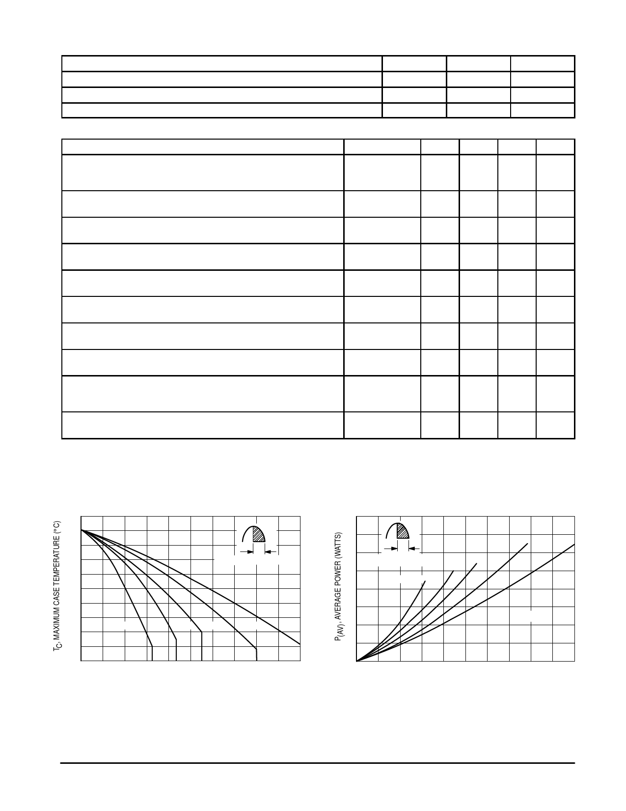
TYPICAL CHARACTERISTICS
130
120
α
α = CONDUCTION ANGLE
110
100
α = 30° 60° 90° 180°
dc
90
80
0
4
8
12
16
20
IT(AV), ON-STATE FORWARD CURRENT (AMPS)
Figure 1. Average Current Derating
32
24
α
α = CONDUCTION ANGLE 60° 90°
α = 30°
16
8
180°
dc
TJ = 125°C
0
0
4
8
12
16
20
IT(AV), AVERAGE ON-STATE FORWARD CURRENT (AMPS)
Figure 2. Maximum On-State Power Dissipation
2
Motorola Thyristor Device Data
Share Link: 