AN-6067(2010_01) Ver la hoja de datos (PDF) - Fairchild Semiconductor
Número de pieza
componentes Descripción
Fabricante
AN-6067
(Rev.:2010_01)
(Rev.:2010_01)
Fairchild Semiconductor

AN-6067 Datasheet PDF : 21 Pages
| |||
AN-6067
Constant Current Output Regulation
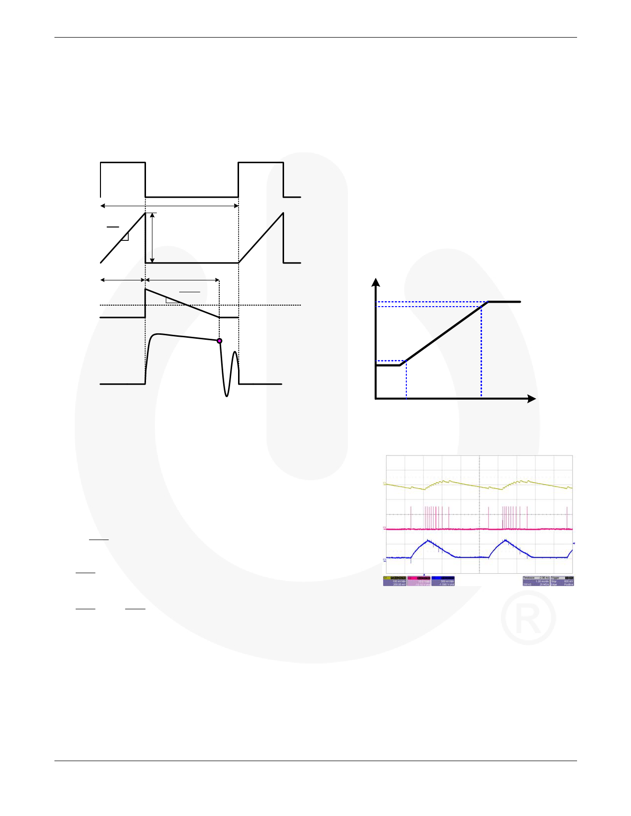
As shown in Figure 12, the output current IO can be
expressed by Equation 1 when the flyback converter is
operated in DCM. As a result, the output current IO can be
calculated by the signal ipk, tdis. The PSR controller then
determines the on-time of the MOSFET to modulate input
power and provide constant output current.
Gate
Vin
iP
Lp
Ts
i pk
ton
iS
IO
tdis
- n2 ⋅Vo
Lp
APPLICATION NOTE
Green-Mode Operation
The proprietary green-mode function of the PSR controller
provides off-time modulation to linearly decrease the PWM
frequency at light-load conditions, as low as 500Hz. With
the green-mode function, the power supply can easily meet
the most stringent of power conservation requirements.
Figure 13 shows the characteristics of the PWM frequency
vs. the output voltage of the error amplifier (VCOMV). The
PSR controller uses the positive, proportional, output load
parameter (VCOMV) as an indication of the output load for
modulating the PWM frequency. In heavy load conditions,
the PWM frequency is fixed at 42KHz. Once VCOMV is lower
than VN, the PWM frequency starts to linearly decrease from
42KHz to 500Hz. Figure 14 is a measured waveform at
burst-mode operation.
Frequency
42KHz
40KHz
sampling voltage
VS
1KHz
500Hz
Figure 12. Principal Operation Waveform of the
Flyback Converter (DCM)
The current-sense resistor can adjust the value of the
constant current. Through better design of the transformer
operations under discontinuous current mode, the PSR
controller’s proprietary control structure is able to achieve
accurate and constant current characteristics. Detailed
design guideline for the transformer is introduced in the
following section.
[ ] Io
=
1
2Ts
⋅
t dis
⋅ is, pk
[ ] =
1
2Ts
⋅
np
⋅ i pk
⋅ tdis
(1)
=
1
2Ts
⋅
⎡
⎢n
⎣
p
⋅ VCS
RCS
⎤
⋅ tdis ⎥
⎦
where:
is,pk is the peak inductor current of the secondary side,
ipk is the peak inductor of primary side.
tdis is discharge-time of transformer inductor current.
np is the turn ratio between primary and secondary winding.
RCS is the current-sense resistor.
VCS is the voltage on current-sense resistor.
VG
VN
VCOMV
Figure 13. PWM Frequency vs. VCOMV
Vo(AC)
100mV/Div
Gate
10V/Div
VCOMV
500mV/Div
Figure 14. Measured Waveform at Burst-Mode Operation
© 2008 Fairchild Semiconductor Corporation
Rev. 1.0.1 • 1/26/10
6
www.fairchildsemi.com
Share Link: