SF51 Ver la hoja de datos (PDF) - DIYI Electronic Technology Co., Ltd.
Número de pieza
componentes Descripción
Fabricante
SF51 Datasheet PDF : 2 Pages
| |||
Features
· Low forward voltage drop
· High current capability
· High reliability
· High surge current capability
· Plastic material-UL flammability 94V-0
Mechanical Data
· Case: Molded plastic DO-201AD
· Terminals: Plated leads solderable per
MIL-STD-202,Method 208 guaranteed
· Polarity: Color band dentes cathode end
· Mounting Position: Any
· Making: Type Number
· Lead Free: For RoHS/Lead Free Version
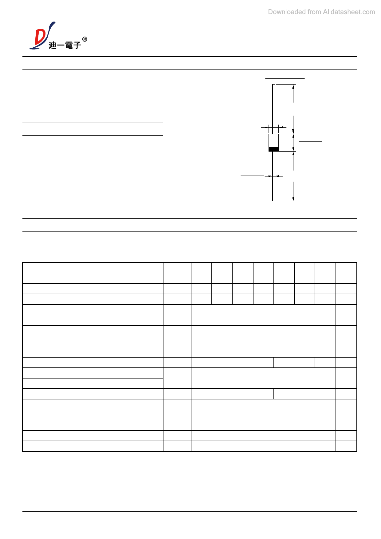
SF51 THRU SF58
5 .0 AMP. Super Fast Rectifiers
DO-201AD
˄˅
DIA.
˄˅
0.96(24.5)
MIN.
˄
˅
˄˅
DIA. ˄˅
˄˅
0.96(24.5)
MIN.
Dimensions in inches and (millimeters)
Maximum Ratings and Electrical Characteristics
Rating at 25℃ ambient temperature unless otherwise specified
Single phase,half wave,60Hz,resistive or inductive load
For capacitive load derate current by 20%
Type Number
SYMBOL SF51 SF52 SF53 SF54 SF55 SF56 SF58 Unit
Maximum Recurrent Peak Reverse Voltage
VRRM 50 100 150 200 300 400 600 V
Maximum RMS Voltage
VRMS 35 70 104 140 210 280 420 V
Maximum DC Blocking Voltage
VDC
50 100 150 200 300 400 600 V
Maximum Average Forward Rectified
Current.375"(9.5mm) lead length@TA=55℃
IO
5.0
A
Peak Forward Surge Current 8.3ms Single half
sine-wave superimposed on rated load (JEDEC IFSM
150
A
Method)
Forward Voltage @IF=5.0A
VFM
Peak Reverse Current @TA=25℃
IR
At Rated DC Blocking Voltage @TA=100℃
Typical Junction Capacitance (Note 1)
CJ
Typical Thermal Resistance Junction to
Ambient(Note 2)
RθJA
Maximum Reverse Recovery Time(Note 3)
Trr
Operating Temperature Range
TJ
/Storage Temperature Range
TSTG
0.95
1.30
5.0
100
90
75
10
35
-55 to +125
-55 to +150
1.7 V
uA
pF
℃/W
ns
℃
℃
Note:1. Measured at 1.0 MHz and Applied reverse Voltage of 4.0V D.C
2. Leads maintained at ambient temperature at a distance of 9.5mm from the case
3.Reverse Recovery Test Conditions: IF=0.5A, IR=1A, Irr=0.25A
version:A0
1of2
www.dyelec.com
Share Link: 