ST75C185 Ver la hoja de datos (PDF) - STMicroelectronics
Número de pieza
componentes Descripción
Fabricante
ST75C185 Datasheet PDF : 16 Pages
| |||
ST75C185
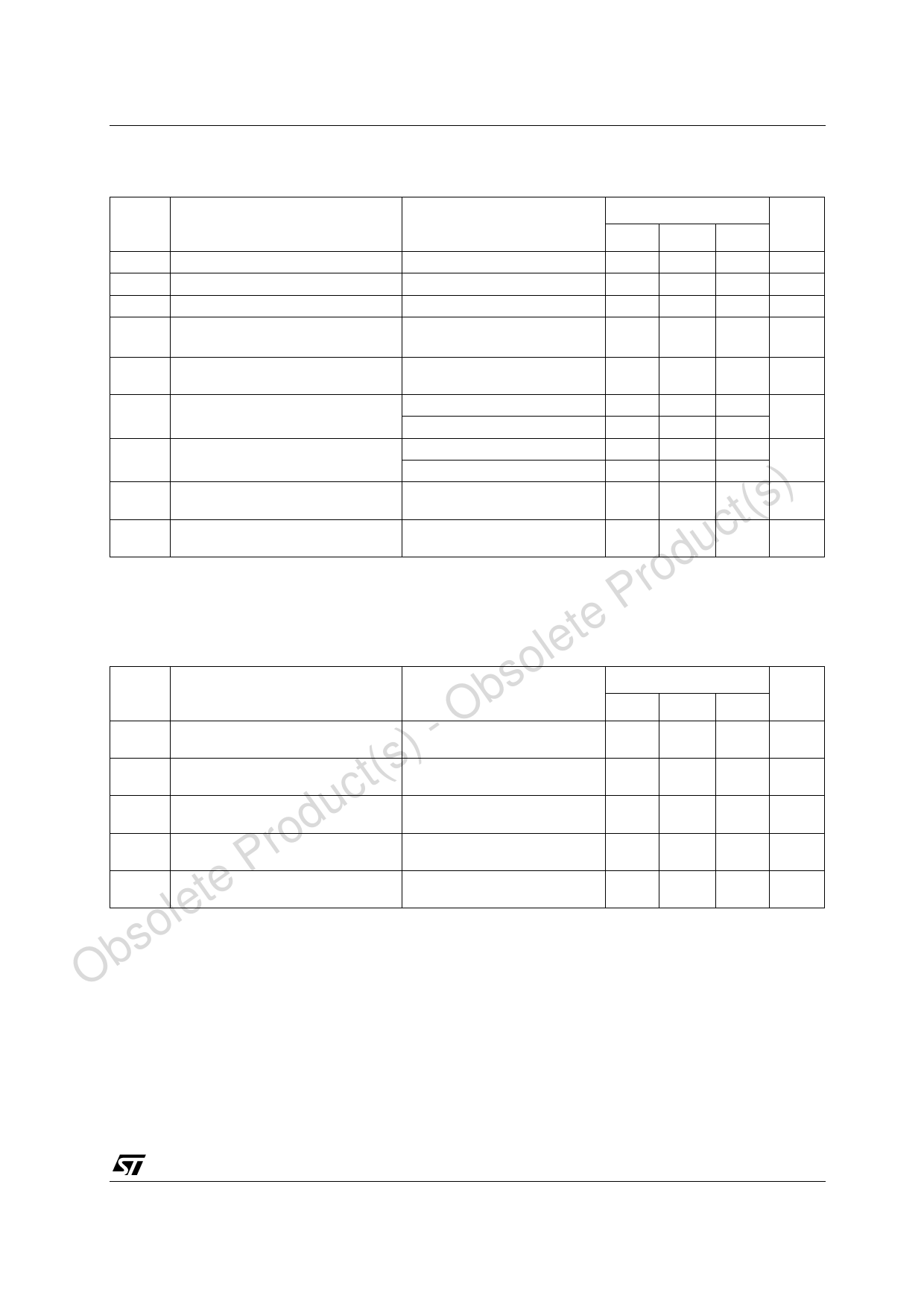
RECEIVER ELECTRICAL CHARACTERISTICS OVER OPERATING TEMPERATURE RANGE
(VDD = 12V, VSS = -12V, VCC = 5V ± 10%, unless otherwise specified)
Symbol
Parameter
Test Conditions
Value
Unit
Min. Typ. Max.
VT+ Positive Going Threshold Voltage (See Figure 6)
1.6
2.1 2.55
V
VT- Negative Going Threshold Voltage (See Figure 6)
0.65
1
1.25
V
Vhys Input Hysteresis (VT+ - VT-) (Note 6)
0.6
1.1
V
VOH High Level Output Voltage (Note 7) IOH = 0.75 mA or Input Open
3.5
4.8
V
IOH = -1 mA (See Figure 6)
VOL Low Level Output Voltage
VI = 3 V IOL = 3.2 mA
(See Figure 6)
0.2
0.4
V
IIH High Level Input Current
VI = 25 V (See Figure 6)
3.6
4.5
8.3
mA
VI = 3 V (See Figure 6)
0.43 0.55
1
IIL Low Level Input Current
VI = -25 V (See Figure 6)
-3.6 -4.4 -8.3 mA
) IOS(H)
uct(s IOS(L)
Short-Circuit Output Current at High
Level
Short-Circuit Output Current at Low
Level
VI = -3 V (See Figure 6)
VI = 0.75 V VO = 0 V
(See Figure 5)
VI = VCC VO = VCC
(See Figure 5)
-0.4 -0.55 -1
-13
-30
mA
35
60
mA
d All typical values are at TA = 25°C
ro NOTE 6: Hysteresis is the difference between the positive going input threshold voltage, VT+, and the negative going input threshold voltage
VT-
P NOTE 7: If the inputs are left unconnected, the receiver interprets this as an input low, and the receiver outputs will remain in the high state.
te RECEIVER SWITCHING CHARACTERISTICS
le (VDD = 12V, VSS = -12V, VCC = 5V ± 10% TA = 25°C)
so Symbol
Parameter
Test Conditions
Ob tPLH
t(s) - tPHL
c tTLH
rodu tTHL
te P tW(N)
Propagation Delay Time Low to High
Level Output
Propagation Delay Time High to Low
Level Output
Transition Time Low to High Level
Output
Transition Time High to Low Level
Output
Pulse Duration of longest pulse
rejection as noise (Note 8)
RL = 5 KΩ CL = 50 pF
(See Figure 6)
RL = 5 KΩ CL = 50 pF
(See Figure 6)
RL = 5 KΩ CL = 50 pF
(See Figure 6)
RL = 5 KΩ CL = 50 pF
(See Figure 6)
RL = 5 KΩ CL = 50 pF
(See Figure 6)
Value
Unit
Min. Typ. Max.
3.2
4
µs
2.6
4
µs
30
100
ns
10
50
ns
1
2.3
4
µs
le NOTE 8: The receiver ignores any positive or negative going pulse that is less than the minimum value of tW(N) and accepts any positive or negative going
Obso pulse greater than the maximum of tW(N).
5/16
Share Link: 