MP02HBN175-10 Ver la hoja de datos (PDF) - Dynex Semiconductor
Número de pieza
componentes Descripción
Fabricante
MP02HBN175-10 Datasheet PDF : 8 Pages
| |||
MP02X175 Series
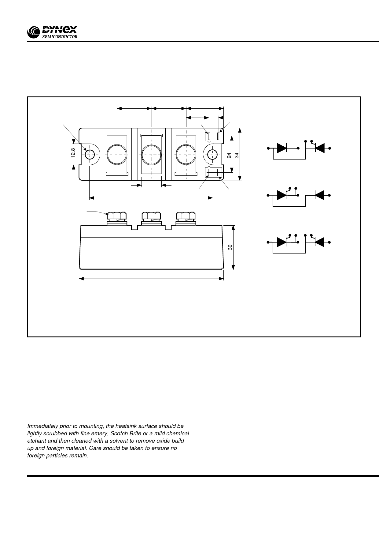
PACKAGE DETAILS
For further package information, please visit our website or contact your nearest Customer Service Centre. All dimensions in mm, unless
stated otherwise. DO NOT SCALE.
2 holes Ø6.5
23
23
24
15
5
K2
G2
1
K2 G2
2
3
Circuit type: HBN
13
G1 K1
80
K1
G1
1
2
3
3x M6
1
2
3
Circuit type: HBP
G1 K1 K2 G2
1
2
3
Circuit type: HBT
94
Nominal weight: 350g
Recommended fixings for mounting: M6 socket head cap screws
Recommended mounting torque: 6Nm (55lb.ins)
Recommended torque for electrical connections: 5Nm (44lb.ins)
Maximum torque for electrical connections: 8Nm (70lb.ins)
Module outline type code: MP02
MOUNTING RECOMMENDATIONS
Adequate heatsinking is required to maintain the base
temperature at 75˚C if full rated current is to be achieved. Power
dissipation may be calculated by use of VT(TO) and rT information
in accordance with standard formulae. We can provide
assistance with calculations or choice of heatsink if required.
The heatsink surface must be smooth and flat; a surface finish
of N6 (32µin) and a flatness within 0.05mm (0.002") are
recommended.
Immediately prior to mounting, the heatsink surface should be
lightly scrubbed with fine emery, Scotch Brite or a mild chemical
etchant and then cleaned with a solvent to remove oxide build
up and foreign material. Care should be taken to ensure no
foreign particles remain.
An even coating of thermal compound (eg. Unial) should be
applied to both the heatsink and module mounting surfaces.
This should ideally be 0.05mm (0.002") per surface to ensure
optimum thermal performance.
After application of thermal compound, place the module
squarely over the mounting holes, (or ‘T’ slots) in the heatsink.
Fit and finger tighten the recommended fixing bolts at each end.
Using a torque wrench, continue to tighten the fixing bolts by
rotating each bolt in turn no more than 1/4 of a revolution at a
time, until the required torque of 6Nm (55lbs.ins) is reached on
all bolts at both ends.
It is not acceptable to fully tighten one fixing bolt before starting
to tighten the others. Such action may DAMAGE the module.
7/8
www.dynexsemi.com
Share Link: 