NTE7018 Ver la hoja de datos (PDF) - NTE Electronics
Número de pieza
componentes Descripción
Fabricante
NTE7018 Datasheet PDF : 6 Pages
| |||
Note 10. The functions in–sync/out–of–sync and transmitter identification have been combined on this pin. The capaci-
tor is charged during the sync pulse and discharged during the time difference between gating and sync pulse.
Note 11. The vertical scan is synchronized by means of a divider system. Therefore no adjustment is required for the
ramp generator. The divider detects whether the incoming signal has a vertical frequency of 50 or 60HZ and
corrects the vertical amplitude.
Note 12. To avoid screenburn due to a collapse of the vertical deflection, a continuous blanking level is inserted into the
sandcastle pulse when the feedback voltage of the vertical deflection is not within the specified limits.
Note 13. Starting point tuner takeover at 1 = 0.2mA. Takeover to be adjusted with a potentiometer of 47kΩ.
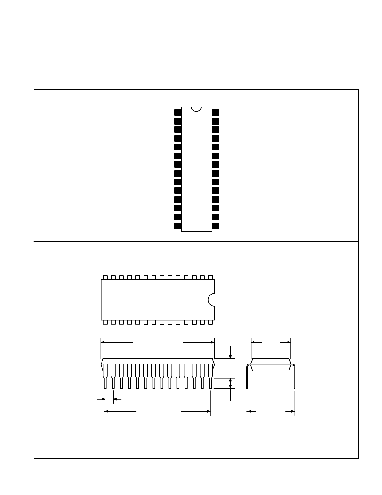
Pin Connection Diagram
AGC Take–over 1
Vertical Ramp Generator 2
Vertical Drive 3
Vertical Feedback 4
Tuner AGC 5
GND 6
VCC 7
Vision IF Input 8
Vision IF Input 9
Decouple Capacitor 10
Volume Control/
Start Horizontal Oscillator
11
Audio Output 12
Sound Demodulator 13
Sound IF Decouple 14
28 Phase 2 Detector
27
Sandcastle Output/
Feedback Input
26 Horizontal Drive
25 Sync Separator
24 Phase 1 Detector
23 Horizontal Oscillator
22 Coincidence Detector Decouple
21 Sync Demodulator
20 Sync Demodulator
19 AGC Detector
18 AFC Output
17 Video Output
16 GND
15 Sound IF Input
14
15
1.469 (37.32)
Max
.100 (2.54)
1.300 (33.02)
1
28
.250
(6.35)
.540
(13.7)
.122
(3.1)
Min
.600
(15.24)
Share Link: 