S13MD01 Ver la hoja de datos (PDF) - Sharp Electronics
Número de pieza
componentes Descripción
Fabricante
S13MD01 Datasheet PDF : 4 Pages
| |||
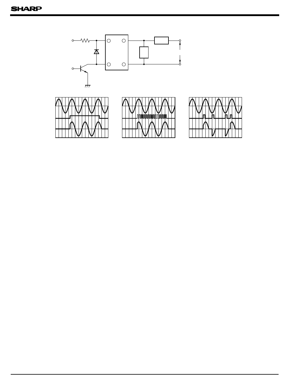
s Basic Operation Circuit
R1
+ VCC
D1
V1
Tr1
2
8
SSR
3
6
Load
ZS
AC 100V(S13MD01)
Zs : Surge absorption circuit
S13MD01
(1) DC Drive
AC supply voltage
Input signal
Load current
(for resistance load)
(2) Pulse Drive
(3) Phase Control
Notes (1) If large amount of surge is loaded onto Vcc or the driver circuit, add a diode D1 between terminals 2 and 3 to prevent reverse
bias from being applied to the infrared LED.
(2) Be sure to install a surge absorption circuit. An appropriate circuit must be chosen according to the load
(for CR, choose its constant). This must be carefully done especially for an inductive load.
(3) For phase control, adjust such that the load current immediately after the input signal is applied will be more than 30mA.
s Precautions for Use
(1) All pins must be soldered since they are also used as heat sinks (heat radiation fins).
In designing, consider the heat radiation from the mounted SSR.
(2) For higher radiation efficiency that allows wider thermal margin, secure a wider round pattern for Pin No. 8
when designing mounting pattern. The rounded part of Pin No. 5 (gate) must be as small as possible.
Pulling the gate pattern around increases the change of being affected by external noise.
q As for other general cautions, refer to the chapter "Precautions for Use" (Page 78 to 93).
Share Link: 