EB-TK2051 Ver la hoja de datos (PDF) - Tripath Technology Inc.
Número de pieza
componentes Descripción
Fabricante
EB-TK2051 Datasheet PDF : 10 Pages
| |||
OPERATING INSTRUCTIONS
Tripath Technology, Inc. - Technical Information
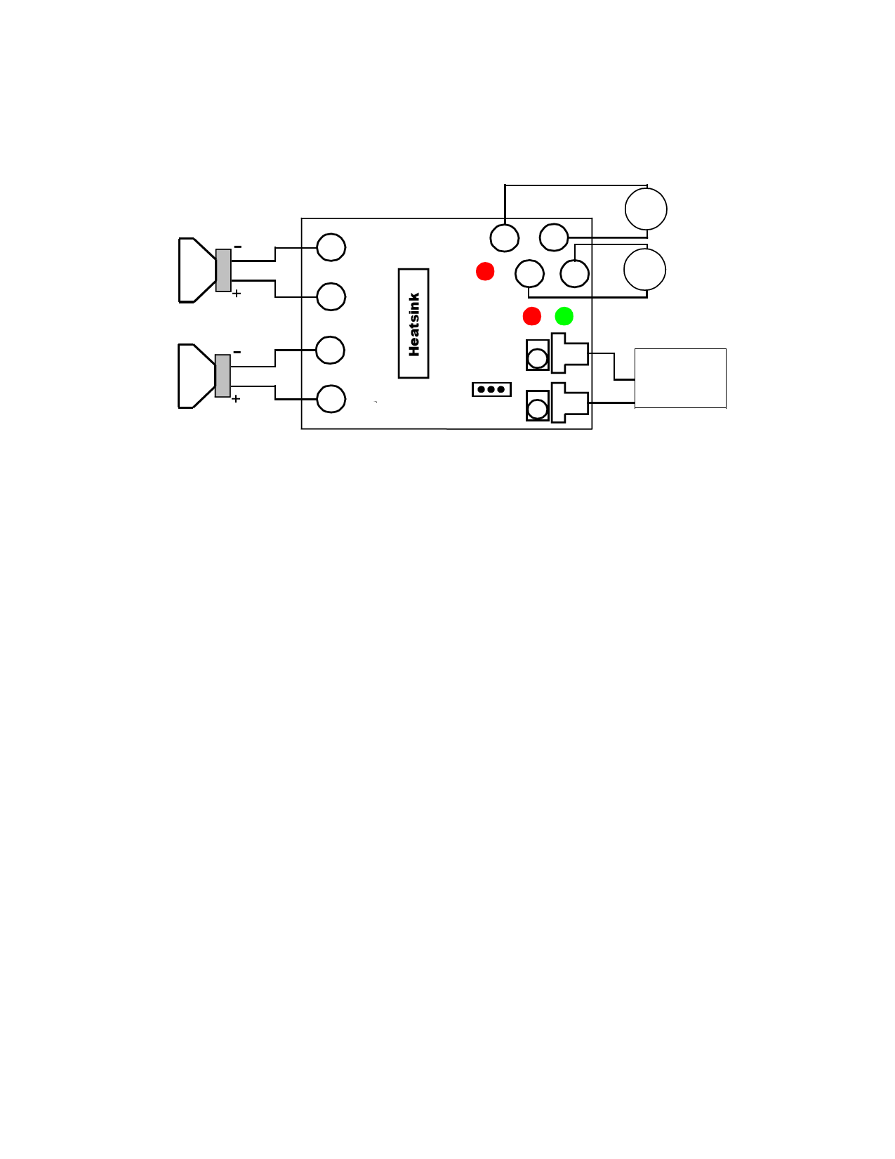
BOARD CONNECTION DIAGRAM
Speaker 1
Speaker 2
- OUT 1
OUT 1 +
- OUT 2
OUT 2 +
VCC
GND
TH - WAR
V5
G5
HMUTE
R16
MUTE
*
R24
G5 V5
* TRIPATH TECHNOLOGY
TK2051 EVAL BOARD rev 1.3
V5
IN1
IN2
+
-
VCC
-
+
V5
Audio Source
OUT1, G5
OUT2, G5
POWER SUPPLIES
Two external power supplies are required to operate the EB-TK2051: VCC (referenced to GND), and V5
(referenced to G5). The V5 ground (G5) must be kept separate from the VCC ground (GND). GND and G5
are joined at a common point on the EB-TK2051 with a 0Ω resistor (R1).
The Minimum and Maximum VCC supply voltages are +10V and +30V, respectively.
The V5 supply voltage is 5V. Please see the TK2051 Data Sheet for Minimum and Maximum values.
The VCC and V5 power supply connections are standard female banana plug connectors. Please refer to
the Board Connection Diagram for the connector locations on the EB-TK2051.
OUTPUT
The output connections for each channel of the EB-TK2051 are made with standard female banana plug
connectors. The output of the TK2051 is differential; therefore each output has a positive output (OUT1+
and OUT2+) and a NEGATIVE OUTPUT (OUT1- AND OUT2-).
Please refer to the Board Connection Diagram for the connector locations on the EB-TK2051.
INPUT
The input connection for each channel of the EB-TK2051 is made using two RCA connectors (female).
The RCA connectors are labeled IN1 and IN2. These inputs share a common ground referenced to G5.
Please refer to the Board Connection Diagram for the connector locations on the EB-TK2051.
JUMPER SETTINGS
There is a 3-pin header for the MUTE control of the TK2051. With the jumper placed in the G5 position the
part is un-muted. When the jumper is placed in the V5 position the mute pin is pulled high (5V) and the
amplifier is muted. Please refer to the Board Connection Diagram for the connector locations on the EB-
TK2051.
3
EB-TK2051 – KL/Rev. 1.0/04.02
Share Link: 