TA7259 Ver la hoja de datos (PDF) - Toshiba
Número de pieza
componentes Descripción
Fabricante
TA7259 Datasheet PDF : 18 Pages
| |||
TA7259P/F/FG
Notes on handling the IC
Motor drive ICs are easily affected by parasitic vibration and unnecessary feedback. This is because the
number of high impedance pins, such as position sensing inputs and control signal inputs, is large, and the
output current value is high and switched.
Moreover, because it is coil loading, care must be taken not to allow the impulse to destroy the IC during
ON/OFF switching. Especially when using a high voltage supply (Vcc is 18V or more), care must be taken not to
apply voltage and current to the output transistor which exceed the specification. Use of a supply voltageof 18V
or less is recommended. Pay particular attention to the notes above when using a supply voltage over 18V.
(1) Notes in designing reliability
ⅰ) Do not expose the output transistor of the internal IC to high voltage and current,
especially, in motor lock status, ON/OFF switching of Vcc, output short-circuiting, etc.)
ⅱ) The output condenser for ringing absorption should be as small as possible because the output
transistor can be destroyed by the charge-discharge current of this condenser. When there is a
problem, adjusting the capacity of the condenser, the connecting position and the connecting method
(delta or star), and inserting a series resistor (of a few Ω to dozens of Ω) to the condenser and series
should provide the oscillating protection explained later.
ⅲ) In mounting to the print-board, do not stress the FIN, and solder for only a few seconds at 260℃.
ⅳ) Using the large earth area of the print-board to release heat from the FIN is effective in ensuring
reliability.
(2) Notes in wiring
To protect from parasitic vibration, design the print-pattern following the method below.
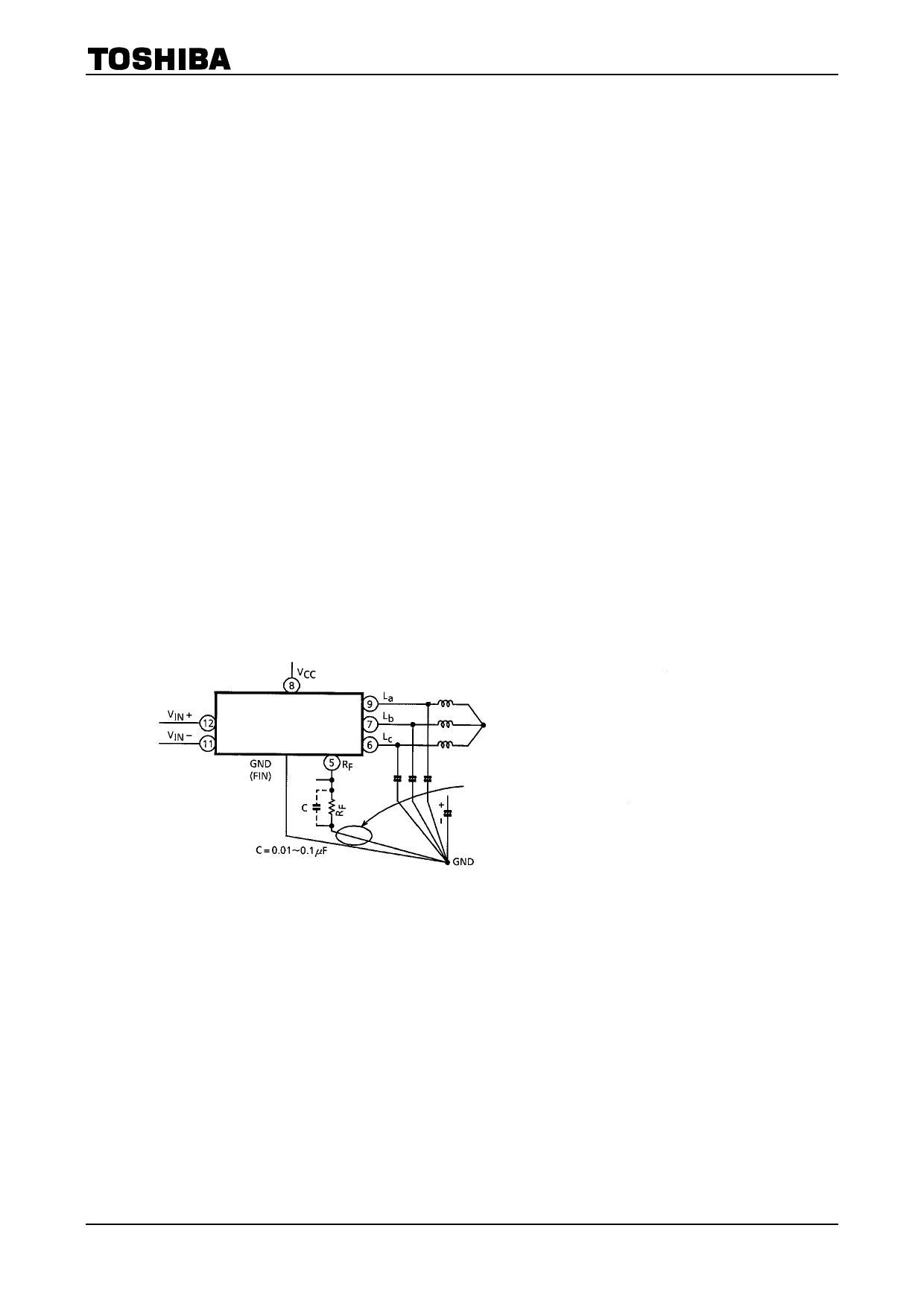
ⅰ) The output coil current path must be separated from other GND lines because a switched high
current flows in this path. It is very important that the line (RF pin→RF resister→GND) should not
be of a common impedance with other circuits.
If the above is impossible or the oscillation cannot be removed completely, connect the condenser
(0.01〜0.1µF) and RF in parallel.
TA7259P/F/FG
Avoid common impedance with other circuits
F図ig2. .2
9
2006-4-14
Share Link: 