CP2114-WM8523EK Ver la hoja de datos (PDF) - Unspecified
Número de pieza
componentes Descripción
Fabricante
CP2114-WM8523EK Datasheet PDF : 26 Pages
| |||
CP2114-EK
DAC Select
JP45
ACTIVE
D6
SUSPEND
D5
RESET
S5
J1
JP48
JP17
JP16
JP15
JP14
JP13
JP12
JP11
JP10
JP40
CP2114
U1
Si500 J2
U3
JP43
SILICON LABS
CP2114-EB
www.silabs.com
PB MUTE REC MUTE VOL -
VOL +
S3
S4
S1
S2
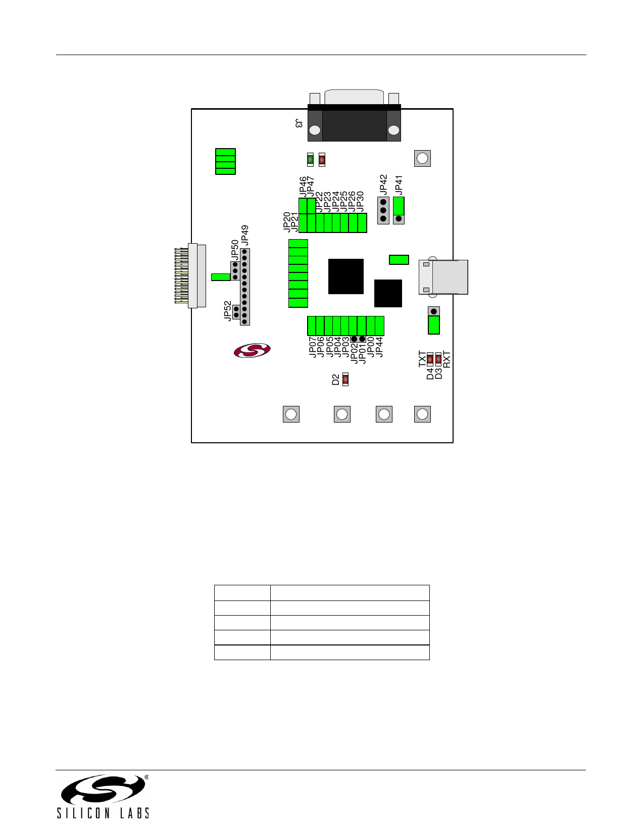
Figure 6. CP2114 Evaluation Board with Default Shorting Blocks Installed
5.1.1. Daughter Card Connector (J1)
The J1 connector is used to connect to a CP2114 daughter card.
5.1.2. Universal Serial Bus (USB) Interface (J2)
A Universal Serial Bus (USB) connector (J2) is provided to facilitate connections to the USB interface on the
CP2114. See Table 2 for the USB pin definitions.
Table 2. USB Connector Pin Descriptions
Pin #
1
2
3
4
Description
VBUS
D–
D+
GND (Ground)
Rev. 0.1
9
Share Link: 