9534 Ver la hoja de datos (PDF) - NXP Semiconductors.
Número de pieza
componentes Descripción
Fabricante
9534 Datasheet PDF : 27 Pages
| |||
NXP Semiconductors
PCA9534
8-bit I2C-bus and SMBus low power I/O port with interrupt
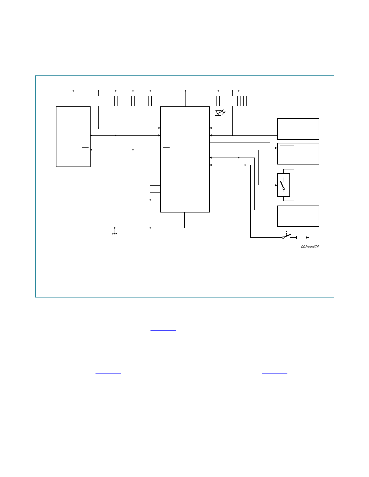
7. Application design-in information
VDD (5 V)
VDD
MASTER
CONTROLLER
SCL
SDA
INT
VSS
5V
10 kΩ
10 kΩ
10 kΩ
10 kΩ
2 kΩ
VDD
PCA9534
SCL
IO0
SDA
IO1
IO2
INT
IO3
IO4
IO5
IO6
IO7
A2
A1
A0
VSS
100 kΩ
(× 3)
SUBSYSTEM 1
(e.g., temp. sensor)
INT
RESET
SUBSYSTEM 2
(e.g., counter)
A
enable
controlled switch
(e.g., CBT device)
B
ALARM
SUBSYSTEM 3
(e.g., alarm system)
Device address configured as 0100 100X for this example.
IO0, IO1, IO2 configured as outputs.
IO3, IO4, IO5 configured as inputs.
IO6, IO7 are not used and must be configured as outputs.
Fig 12. Typical application
VDD
002aac476
7.1 Minimizing IDD when the I/O us used to control LEDs
When the I/Os are used to control LEDs, they are normally connected to VDD through a
resistor as shown in Figure 12. Since the LED acts as a diode, when the LED is off the
I/O VI is about 1.2 V less than VDD. The supply current, IDD, increases as VI becomes
lower than VDD.
Designs needing to minimize current consumption, such as battery power applications,
should consider maintaining the IOn pins greater than or equal to VDD when the LED is off.
Figure 13 shows a high value resistor in parallel with the LED. Figure 14 shows VDD less
than the LED supply voltage by at least 1.2 V. Both of these methods maintain the I/O VI
at or above VDD and prevents additional supply current consumption when the LED is off.
PCA9534
Product data sheet
All information provided in this document is subject to legal disclaimers.
Rev. 4 — 7 November 2017
© NXP Semiconductors N.V. 2017. All rights reserved.
11 of 27
Share Link: 