LR745 Ver la hoja de datos (PDF) - Microchip Technology
Número de pieza
componentes Descripción
Fabricante
LR745 Datasheet PDF : 15 Pages
| |||
LR745
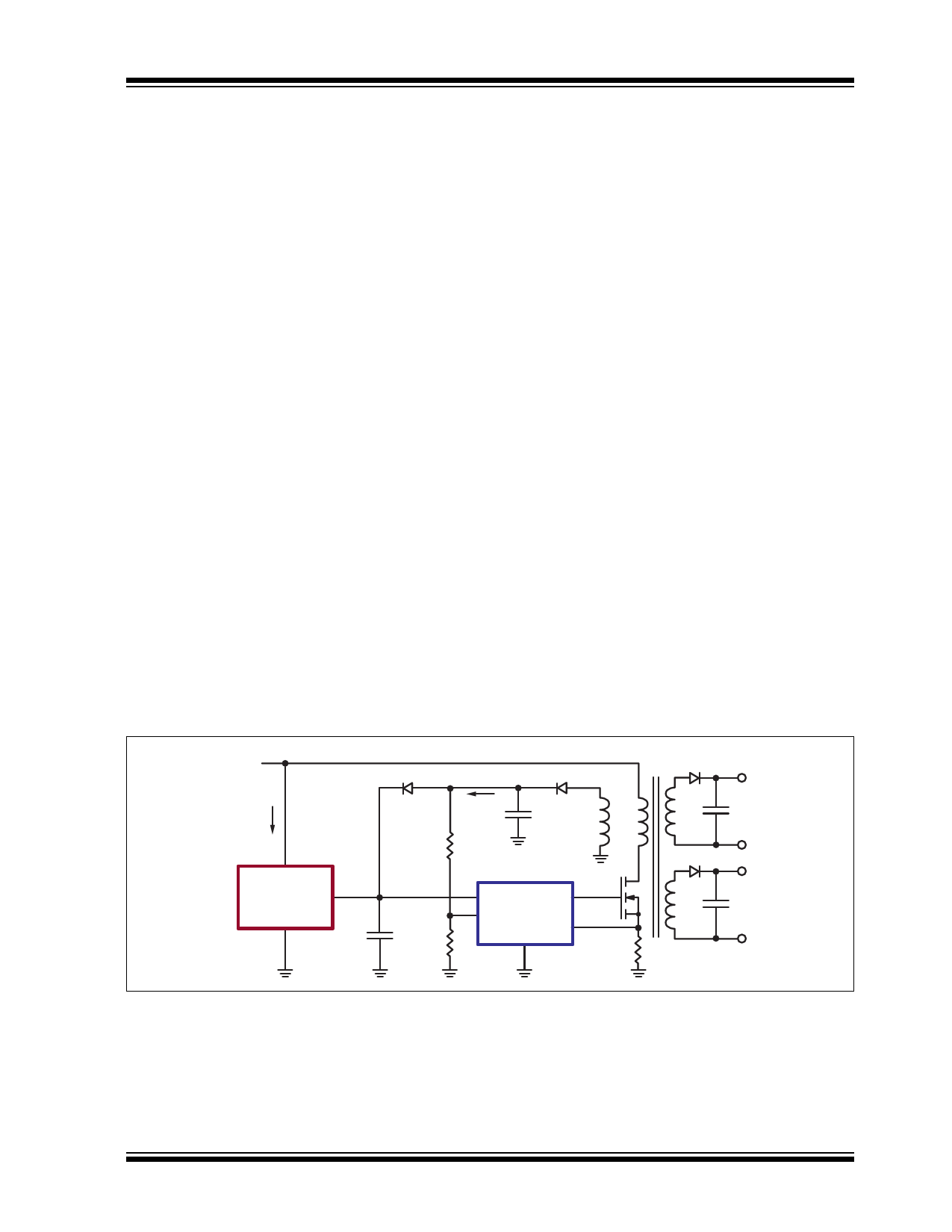
3.0 APPLICATION INFORMATION
Figure 3-1 shows a simplified typical configuration of a
switch mode power supply, SMPS, using LR745 in the
start-up circuit.
LR745’s VOUT terminal is connected to the VCC line of
a PWM IC. An auxiliary winding on the transformer
generates a VCC voltage to power the PWM IC after
start-up. LR745 supplies power for the PWM IC only
during start-up. After start-up, LR745 turns off and the
auxiliary winding supplies power for the PWM IC.
Figure 3-2 shows the typical current and voltage wave-
forms at various stages from power-up to operation
powered by the auxiliary winding.
3.1 Stage I
Once a voltage is applied on VIN, LR745 starts to
charge the VCC capacitor, C1. The VCC voltage starts to
increase at a rate limited by the internal current limiter
of 3.0mA. The PWM IC is in its start-up condition and
will typically draw 0.5mA from the VCC line. The VCC
voltage will continue to increase until it reaches the
PWM IC’s start threshold voltage, typically 16V.
3.2 Stage II
Once VCC reaches 16V, the PWM IC is in its operating
condition and will typically draw 20mA, depending on
the operating frequency and size of the switching
metal–oxide–semiconductor field-effect transistor
(MOSFET). The output of LR745, VOUT, is internally
current limited to 3.0mA. The remaining 17mA will be
supplied by C1, causing the VCC voltage decrease.
When VCC decreases to 13.25V, LR745 will turn off its
output, thereby reducing its input current from 3.0mA to
10s of microamperes. At this point, all 20mA will be
supplied by C1. The PWM IC can now operate to a min-
imum VCC voltage, typically 10V.
Once the switching MOSFET starts operating, the
energy in the primary winding is transferred to the sec-
ondary outputs and the auxiliary winding, thereby build-
ing up VAUX. It is necessary to size the VCC storage
capacitor, C1, such that VAUX increases to a voltage
greater than 10V before VCC decreases to 10V. This
allows VAUX to supply the required operating current for
the PWM IC.
If for some reason the auxiliary voltage does not reach
10V, VCC will continue to decrease. Once VCC goes
below 10V, the PWM IC will return to its start-up condi-
tion. The PWM IC will now only draw 0.5mA. VCC will
continue to decrease but at a much slower rate. Once
VCC decreases below 7.0V, LR745 will turn the output,
VOUT, back on. VOUT will start charging C1 as described
in Stage I.
3.3 Stage III
At this stage, LR745 output is turned off and the PWM
IC is operating from the VAUX supply. The auxiliary volt-
age, VAUX, can be designed to vary anywhere between
the minimum operating VCC voltage of the PWM IC
(10V) to the maximum auxiliary voltage rating of the
LR745 (22V).
FIGURE 3-1:
SIMPLIFIED SMPS USING LR745
VIN
IIN
High Voltage
VAUX
IAUX
C2 D2
LR7
VOUT
VCC
GND
C1
PWM IC
2015 Microchip Technology Inc.
DS20005394A-page 5
Share Link: 