ADM705ANZ(2016) Ver la hoja de datos (PDF) - Analog Devices
Número de pieza
componentes Descripción
Fabricante
ADM705ANZ Datasheet PDF : 8 Pages
| |||
Data Sheet
ADM705/ADM706/ADM707/ADM708
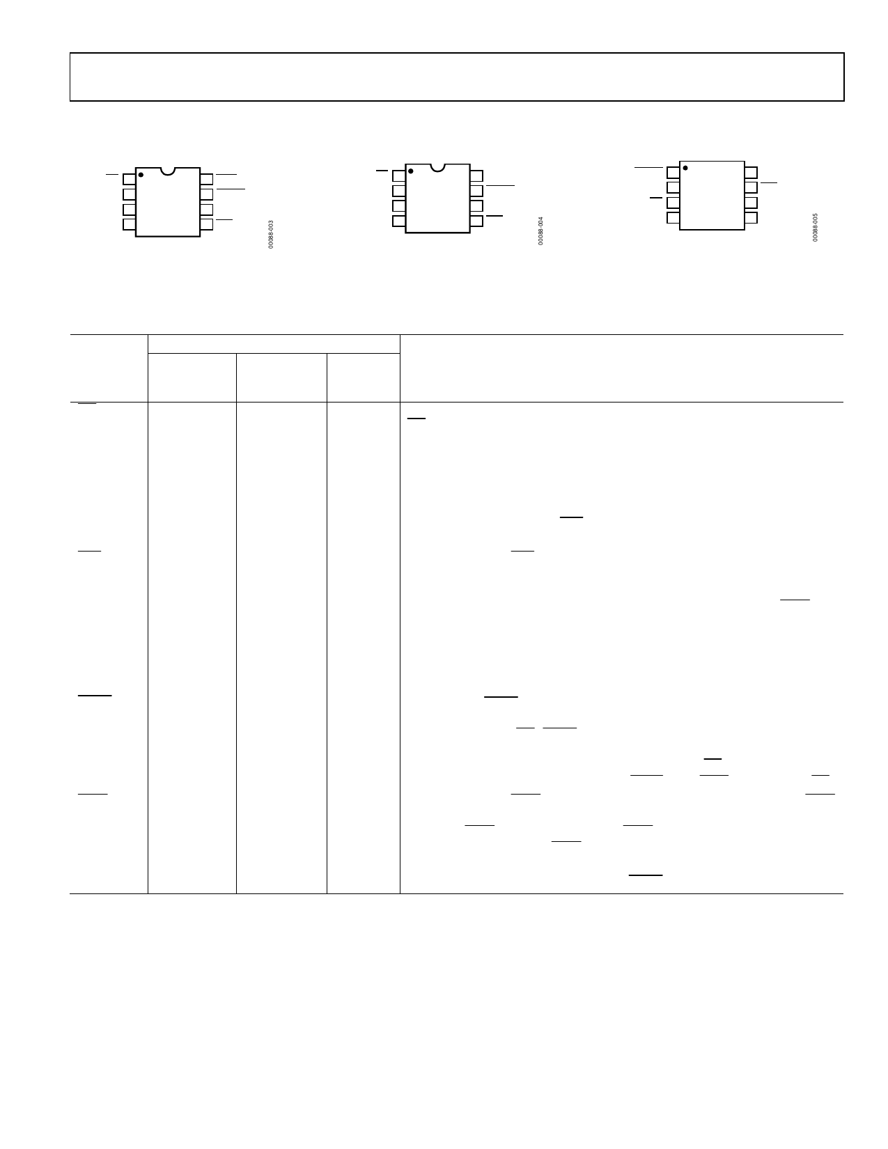
PIN CONFIGURATIONS AND FUNCTION DESCRIPTIONS
MR 1 ADM705/ 8 WDO
VCC 2 ADM706 7 RESET
GND 3 TOP VIEW 6 WDI
PFI 4 (Not to Scale) 5 PFO
Figure 3. ADM705/ADM706 PDIP/SOIC
Pin Configuration
MR 1 ADM707/ 8 RESET
VCC 2 ADM708 7 RESET
GND 3 TOP VIEW 6 NC
PFI 4 (Not to Scale) 5 PFO
NC = NO CONNECT
Figure 4. ADM707/ADM708 PDIP/SOIC
Pin Configuration
RESET 1 ADM708 8 NC
RESET 2
7 PFO
MR 3 TOP VIEW 6 PFI
VCC 4 (Not to Scale) 5 GND
NC = NO CONNECT
Figure 5. ADM708 MSOP
Pin Configuration
Table 3. Pin Function Descriptions
Pin Number
ADM705/ ADM707/
ADM706 ADM708 ADM708
Mnemonic (PDIP, SOIC) (PDIP, SOIC) (MSOP) Description
MR
1
1
3
Manual Reset Input. When this pin is taken below 0.8 V, a reset is generated. MR can be
driven from TTL, CMOS logic, or from a manual reset switch as it is internally debounced.
An internal 250 μA pull-up current holds the input high when floating.
VCC
2
2
4
5 V Power Supply Input. Place a 0.1 μF decoupling capacitor between the VCC and GND pins.
GND
3
3
5
0 V Ground Reference for All Signals.
PFI
4
4
6
Power Fail Input. PFI is the noninverting input to the power fail comparator. When PFI is
less than 1.25 V, PFO goes low. If unused, PFI must be connected to GND.
PFO
5
5
7
Power Fail Output. PFO is the output from the power fail comparator. It goes low when
PFI is less than 1.25 V.
WDI
6
Not
applicable
Not
Watchdog Input. WDI is a three-level input. If WDI remains either high or low for longer
applicable than the watchdog timeout period, the watchdog output (WDO) goes low. The timer
resets with each transition at the WDI input. Either a high to low or a low to high transition
clears the counter. The internal timer is also cleared whenever reset is asserted. The
watchdog timer is disabled when WDI is left floating or connected to a three-state buffer.
NC
Not
6
applicable
8
No Connect.
RESET
7
7
1
Logic Output. RESET goes low for 200 ms when triggered. It can be triggered either by
VCC being below the reset threshold or by a low signal on the manual reset input (MR).
RESET remains low whenever VCC is below the reset threshold (4.65 V in ADM705/ADM707,
4.40 V in ADM706/ADM708). It remains low for 200 ms after VCC goes above the reset
threshold or MR goes from low to high. A watchdog timeout does not trigger RESET unless
WDO is connected to MR.
WDO
8
Not
applicable
Not
Watchdog Output. WDO remains low until the watchdog timer is cleared. WDO also
applicable goes low during low line conditions. Whenever VCC is below the reset threshold, WDO
goes low if the internal WDO remains low. As soon as VCC goes above the reset threshold,
WDO goes high.
RESET
Not
8
applicable
2
Logic Output. RESET is an active high output suitable for systems that use active high
reset logic. It is the inverse of RESET.
Rev. H | Page 5 of 12
Share Link: 