LNK6663E(2014) Ver la hoja de datos (PDF) - Power Integrations, Inc
Número de pieza
componentes Descripción
Fabricante
LNK6663E
(Rev.:2014)
(Rev.:2014)
Power Integrations, Inc

LNK6663E Datasheet PDF : 24 Pages
| |||
LinkSwitch-HP
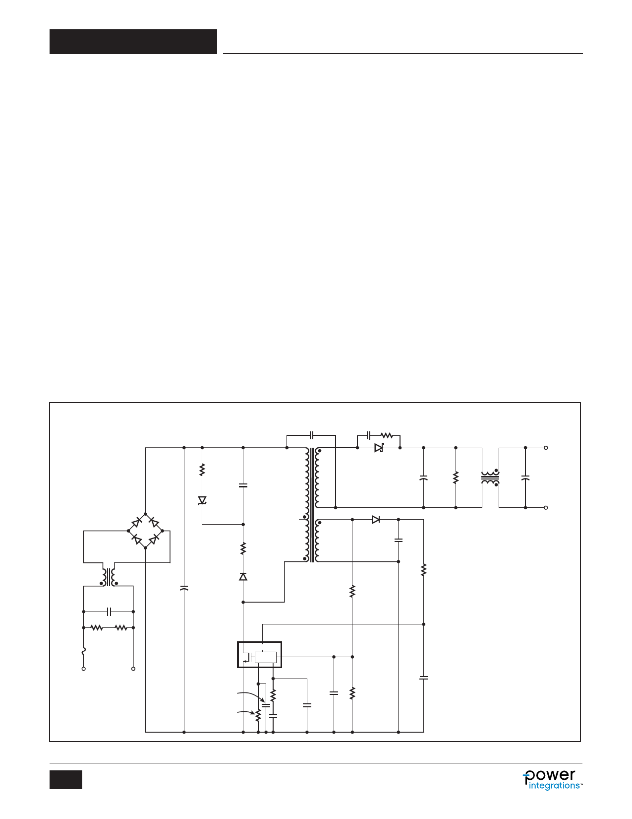
Applications Example
30 W, 12 V Universal Adapter
The circuit shown in Figure 11 is a high efficiency universal input
30 W, 12 V output adapter using the LNK6766E.
The supply uses primary winding coupled sensing for the
following features: output regulation, line undervoltage lockout,
input and output OVP. With primary winding sense there is no
need for an external secondary referenced error amplifier such
as a TL431 and optocoupler. The winding sense of bus voltage
also eliminates the need for direct input voltage sensing which
requires more components and is more dissipative than winding
sense method.
Output regulation is ±5%, active-on efficiency is 86% and
no-load input power is less than 30 mW.
The rectified and filtered input voltage is applied to the primary
winding of T1. The other side of the primary is driven by the
integrated power MOSFET in U1. Diode D1, C3, R2, R3 and
VR1 comprise the clamp circuit, limiting the leakage inductance
turn-off voltage spike to safe value. Zener diode VR1 also helps
to reduce input power consumption during no-load conditions.
Start-up of the power supply is initiated by sensing the forward
negative pulse current from feedback winding through R19 into
the FEEDBACK pin. This sensing is accomplished by periodically
turning on the power MOSFET to sense input voltage condition
with very short low frequency sampling pulses. During the
forward pulse sampling time the FEEDBACK pin is held to zero
volts by an internal clamp. When negative forward pulse current
exceeds 250 mA, LinkSwitch-HP for two consecutive switching
cycles will initiate start-up with a soft-start sequence that reduces
component stress and allows the output to rise in a smooth
monotonic manner. The desired input voltage for start-up is
determined by the turns ratio of primary winding to feedback
winding and the value of R19.
Regulation is accomplished by sampling the feedback winding
during flyback period through the resistor divider R19 and R20
through FEEDBACK pin. This sampled voltage is compared to
an internal error amplifier threshold of 2 V. The value of R19 is
already determined by the line undervoltage function so the
output regulation point is determined by setting the proper
value for R20.
The loop compensation is provided by the network from
COMPENSATION pin to ground. In the case above, a low
frequency to mid frequency gain of 20 dB for the error amplifier
is established by R7 and C7. Capacitor C8 functions essentially
as a noise filter and is typically 100 pF. There is also an internal
16 kHz filter within the device. It is advised to limit R7 to no
greater than 260 kW to avoid stability and noise sensitivity.
BR2
DF206ST-G
600 V
L4
10 mH
C14
150 nF
275 VAC
C2
68 µF
400 V
R3
3 kΩ
VR1
BZG03C130
130 V
C3
10 nF
630 V
R2
100 Ω
1/2 W
D1
DL4937
C18
2.2 nF
250 VAC
9
FL1
FL2
7
6
8
T1
RM8
C13 R13
680 pF 20 Ω
100 V 1/8 W
D8
STPS30100ST
L5
100 µH
12 V, 2.5 A
J3
C12
1000 µF
16 V
R28
27 kΩ
C22
10 µF
16 V
D2
BAV21WS-
7-F
R19
41.2 kΩ
1%
C6
22 µF
16 V
R9
4.3 kΩ
1%
1/8 W
RTN
J4
R29 R30
3.3 MΩ 3.3 MΩ
F1
2A
90 - 265
VAC
J1
J2
D
LinkSwitch-HP
U1
LNK6766E
S
BP
CONTROL
FB
PD CP
C20
4.7 nF
50 V
R8
23.2 kΩ
1%
1/8 W
R7
100 kΩ
1/8 W
C7
100 nF
25 V
C23
10 pF
50 V
C8
100 pF
50 V
Figure 11. Schematic of a Universal Input 30 W, 12 V, 2.5 A Adapter.
8
Rev. C 03/14
R20
10.2 kΩ
1%
C5
470 nF
50 V
PI-6844-120312
www.powerint.com
Share Link: