LNK6663E(2014) Ver la hoja de datos (PDF) - Power Integrations, Inc
Número de pieza
componentes Descripción
Fabricante
LNK6663E
(Rev.:2014)
(Rev.:2014)
Power Integrations, Inc

LNK6663E Datasheet PDF : 24 Pages
| |||
LinkSwitch-HP
132
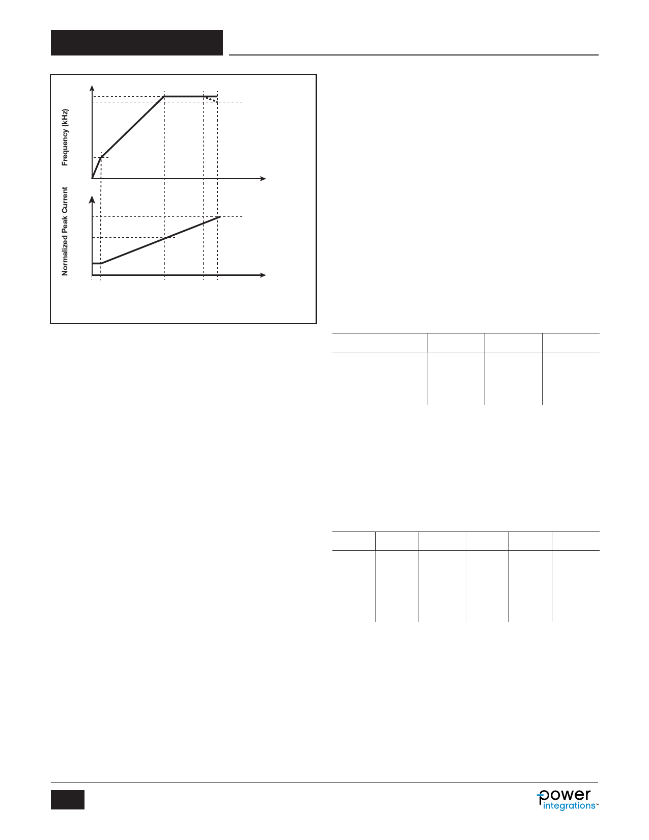
fSW(LF)
32
100%
50%
Compensation
Voltage (∝ POUT)
25%
VC(MIN) VC(MCM)
VC(MAX)
Compensation
Voltage (∝ POUT)
PI-6722-111212
Figure 5. Compensation Pin Characteristics (Multi-Mode Operation).
Auto-Restart
In the event of an open-loop fault (no connection between the
feedback winding and the feedback divider network or the
FEEDBACK pin to the feedback network), the sensed current
out of FEEDBACK pin will be zero during MOSFET on-time, the
device enters into line brown-out protection (line UV). In the
event of output short-circuit or overload condition, the device
enters into auto-restart mode. Auto-restart minimizes the
power dissipation under fault conditions, the device will turn on
and off at duty cycle of typically 3% as long as the fault condition
persists. In auto-restart switching is disabled for tAR(OFF)1
(typ. 150 ms) when the FEEDBACK pin voltage has dropped
below the auto-restart threshold VFB(AR) for the shutdown default
delay time tAR(ON) (typ. 35 ms). After this period switching is
enabled again with the device entering soft-start (typ. 15 ms).
For the first auto-restart off-period switching is disabled for a
reduced time tAR(OFF)2 (typ. 1500 ms) to reduce the power supply
restart time during line cycling. Optionally the default shutdown
delay time can be extended by adding a capacitor to the
PROGRAM pin.
Hysteretic Thermal Shutdown
The thermal shutdown circuitry senses the controller die
temperature. The threshold is set at 142 °C with a 75 °C
hysteresis (both typical). Once the device temperature rises
above 142 °C, the power MOSFET is disabled and remains
disabled until the die temperature falls by 75 °C, at which point
the device is re-enabled. The large hysteresis maintain the
average temperature below the temperature rating of low cost
CEM type PCB material in most cases.
Safe Operating Area (SOA) Protection
The device features a safe operating area (SOA) protection
mode which disables MOSFET switching for 4 consecutive
cycles in the event the peak switching current reaches the
current limit in less than time tON(SOA). This prevents excessive
drain currents during start-up and output short-circuit conditions
by providing additional time for the primary inductance to reset.
The SOA protection is disabled when the output voltage is
within 7.5% of regulation voltage.
Sample and Hold (S/H)
The sample and hold block senses the output voltage at auxiliary
winding during secondary rectifier on-time. The FEEDBACK pin
voltage is sampled after the turn-off of the internal switch to
compensate for diode conduction time differences. Sampling
time increases monotonically from 1.2 ms at no or light load to
2.5 ms at full load. Sampled voltage is held until the next clock
cycle. The output of S/H is fed to the error amplifier, once in
regulation the sampled voltage is 2 V.
BYPASS (BP) Programming
This feature selects either hysteretic or latching OVP/OCP and
OTP protection based on capacitor loading on the BYPASS pin.
The shutdown type is determined at the device power-up as
shown in Table 3.
CBP
OVP
Lost Regulation
(SC, OC)
OTP
0.47 mF
4.7 mF
Latching Auto-Restart
Auto-Restart Auto-Restart
Latching Hysteretic
47 mF
Latching
Latching
Latching
Table 3. Shutdown Type vs. Value of BYPASS Pin Capacitance.
Current Limit Setting
During power-up the cycle-by-cycle current limit is determined
by measuring the resistor value connected to the PROGRAM
pin by the measurement is performed by applying 1.25 V (see
Figure 10). The current limit can be set between 40% to 100%
in steps of 10% as shown in Table 4. After the current limit is
set the PROGRAM pin voltage is reduced to ~0 in order to
minimize power dissipation.
IPD
RPD
ILIMIT(NORM)
IPD
RPD
ILIMIT(NORM)
mA
kW
%
mA
kW
%
10
124
100
54
23.2
60
16
78.7
90
83
15.0
50
24
52.3
80
125
10.0
40
36
34.8
70
Table 4. Current Limit Selection vs. Program Pin Resistor Value.
Programmable Shutdown Delay
The default auto-restart shutdown delay time tSD(AR) (typ. 35 ms)
can optionally be extended by connecting a capacitor to the
PROGRAM pin. Once a lost regulation fault is detected the
PROGRAM pin voltage is cycled 128 times between VPD(DL) (typ.
0.5 V) and VPD(DU) (typ. 1.2 V) as shown in Figure 10. Figure 6
depicts the relationship between extended shutdown delay
time, added PROGRAM pin capacitor and current limit
programming resistor.
4
Rev. C 03/14
www.powerint.com
Share Link: