LTC1069-7(1996) Ver la hoja de datos (PDF) - Linear Technology
Número de pieza
componentes Descripción
Fabricante
LTC1069-7 Datasheet PDF : 8 Pages
| |||
LTC1069-7
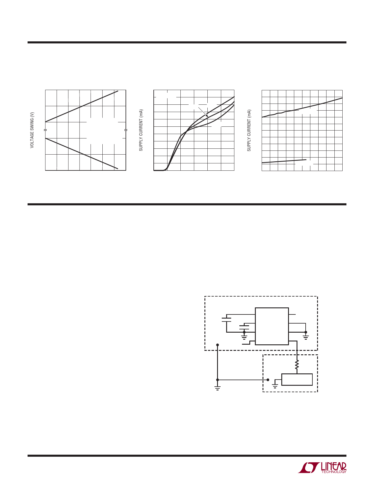
PIN FUNCTIONS
AGND (Pin 1): Analog Ground. The quality of the analog
signal ground can affect the filter performance. For either
single or dual supply operation, an analog ground plane
surrounding the package is recommended. The analog
ground plane should be connected to any digital ground at
a single point. For dual supply operation, Pin 1 should be
connected to the analog ground plane.
For single supply operation, Pin 1 should be bypassed to
the analog ground plane with a capacitor 0.47µF or larger.
An internal resistive divider biases Pin 1 to half the total
power supply. Pin 1 should be buffered if used to bias
other ICs. Figure 1 shows the connections for single
supply operation.
V+, V – (Pins 2, 7): Power Supplies. The V+ (Pin 2) and V –
(Pin 7) should be bypassed with a 0.1µF capacitor to an
adequate analog ground. The filter’s power supplies should
be isolated from other digital or high voltage analog
supplies. A low noise linear supply is recommended.
Using switching power supplies will lower the signal-to-
noise ratio of the filter. Unlike previous monolithic filters,
the power supplies can be applied in any order, that is, the
positive supply can be applied before the negative supply
and vice versa. Figure 2 shows the connections for dual
supply operation.
NC (Pins 3, 6): No Connection. Pins 3 and 6 are not connected
to any internal circuitry; they should be tied to ground.
VIN (Pin 4): Filter Input. The filter input pin is internally
connected to the inverting inputs of two op amps through
a 36k resistor for each op amp. This parallel combination
creates an 18k input impedance.
CLK (Pin 5): Clock Input. Any TTL or CMOS clock source
with a square wave output and 50% duty cycle (±10%) is
an adequate clock source for the device. The power supply
for the clock source should not necessarily be the filter’s
power supply. The analog ground of the filter should only
be connected to the clock’s ground at a single point. Table
1 shows the clock’s low and high level threshold value for
a dual or single supply operation. A pulse generator can be
used as a clock source provided the high level on-time is
greater than 0.42µs (VS = ± 5V). Sine waves less than
100kHz are not recommended for clock sources because
excessive slow clock rise or fall times generate internal
clock jitter. The maximum clock rise or fall time is 1µs. The
clock signal should be routed from the right side of the IC
package to avoid coupling into any input or output analog
signal path. A 1k resistor between the clock source and the
clock input (Pin 5) will slow down the rise and fall times of
the clock to further reduce charge coupling, Figure 1.
Table 1. Clock Source High and Low Thresholds
POWER SUPPLY
HIGH LEVEL
LOW LEVEL
Dual Supply = ±5V
1.5V
0.5V
Single Supply = 10V
6.5V
5.5V
Single Supply = 5V
1.5V
0.5V
VOUT (Pin 8): Filter Output. Pin 8 is the output of the filter,
and it can source 23mA or sink 16mA. The total harmonic
distortion of the filter will degrade when driving coaxial cables
or loads less than 20k without an output buffer.
ANALOG GROUND
PLANE
0.47µF
V+
0.1µF
VIN
1 AGND
VOUT 8 VOUT
2 V+
V– 7
3
LTC1069-7
NC
NC
6
4 VIN
CLK 5
ANALOG GROUND
PLANE
1 AGND
8
VOUT
VOUT
V+
2 V+
V– 7
V–
0.1µF
3
LTC1069-7
NC
NC
6
0.1µF
VIN 4 VIN
CLK 5
STAR
SYSTEM
GROUND
DIGITAL
GROUND
PLANE
1k
CLOCK
SOURCE
STAR
SYSTEM
GROUND
DIGITAL
GROUND
PLANE
1k
CLOCK
SOURCE
LTC1069-7 • F01
Figure 1. Connections for Single Supply Operation
LTC1069 F02
Figure 2. Connections for Dual Supply Operation
6
Share Link: 