STK57FU391A-E Ver la hoja de datos (PDF) - ON Semiconductor
Número de pieza
componentes Descripción
Fabricante
STK57FU391A-E Datasheet PDF : 16 Pages
| |||
STK57FU391A-E
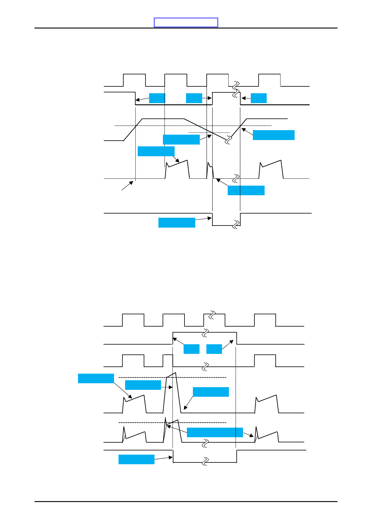
Input / Output Timing Chart
UVLO(under Voltage Lockout) protection
LIN/PFCIN
Protection state
Reset
Set
Reset
Control supply voltage VD
Under voltage trip
Normal operation
Under voltage reset
Output Current Ic (A)
After the voltage level reaches UV reset, the circuits start to
operate when next input is applied .
Fault output
Fault output
<Fig.7>
IGBT turn off
*1 : When VDD decreases all gate output signals will go low and cut off all 6 IGBT outputs. When VDD rises the operation will
resume immediately.
*2 : When the upper side voltage at VB1, VB2 and VB3 drops only the corresponding upper side output is turned off. The outputs
return to normal operation immediately after the upper side gate voltage rises.
Over current protection (ITRIP/PFCTRIP).
HIN/LIN/PFCIN
Protection state
DRVH/DRVL/DRPFC
Set
Reset
Normal operation
Over current
detection
Over current
IGBT turn off
Output Current Ic (A)
Voltage of
Shunt resistor
Fault output
Fault output
Over current reference voltage
RC circuit time constant
<Fig.8>
*1 : When VITRIP exceeds threshold all IGBT’s are turned off and normal operation resumes 2ms (typ) after over current condition is
removed.
No.A2240-9/16
Share Link: 