STK57FU391A-E Ver la hoja de datos (PDF) - ON Semiconductor
Número de pieza
componentes Descripción
Fabricante
STK57FU391A-E Datasheet PDF : 16 Pages
| |||
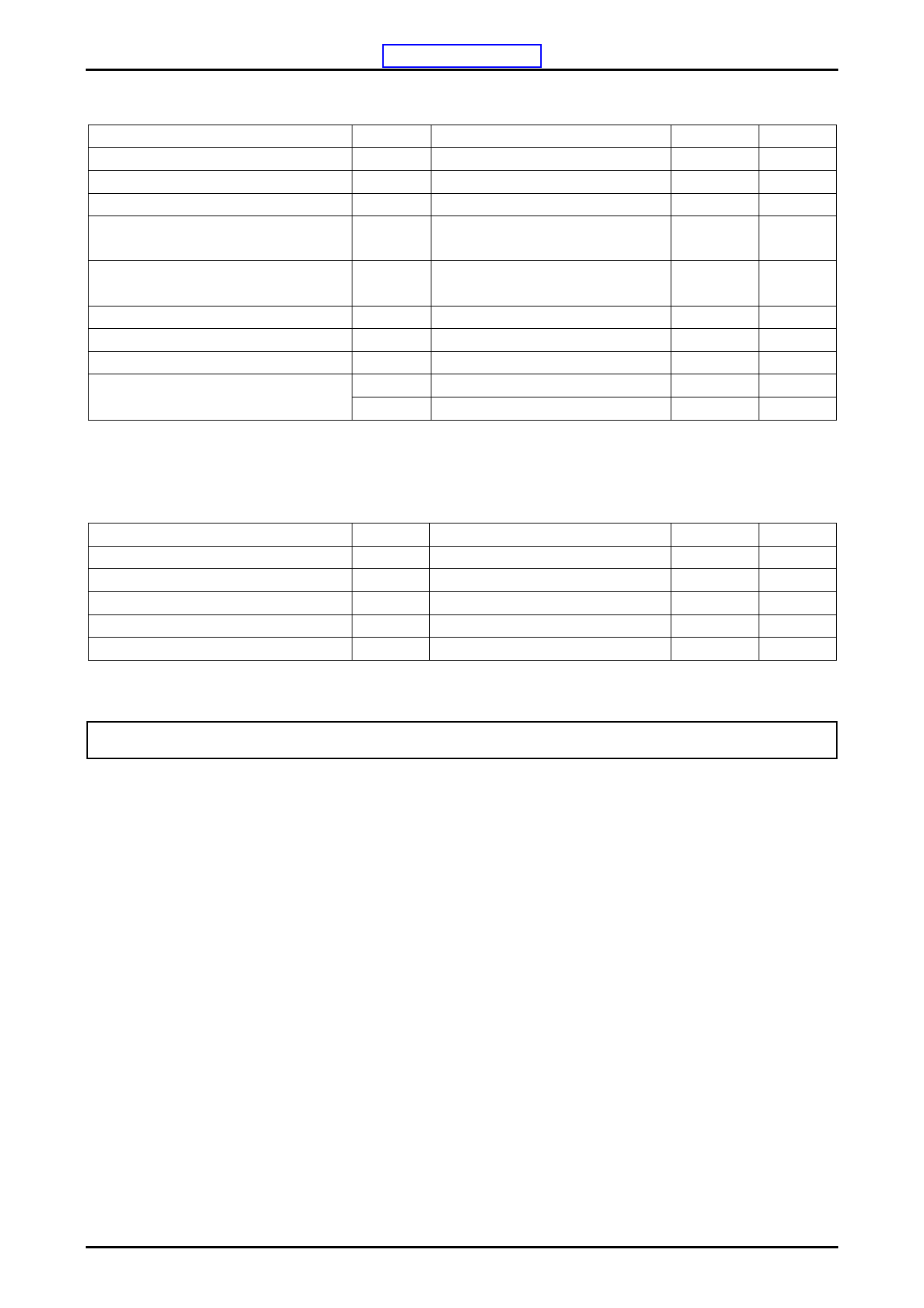
STK57FU391A-E
(2) Inverter Part
Parameter
Supply voltage
Collector-emitter voltage
Output current
Symbol
VCC
VCE
IO
Conditions
+ to U-(V-,W-), surge < 500V *1
+ to U(V,W) or U(V,W) to U-(V-,W-)
+,U-,V-,W-,U,V,W terminal current
Ratings
450
600
±15
Output peak current
IOP
+,U-,V-,W-,U,V,W terminal current
PW=100uSec
±30
Pre-driver supply voltage
VD1,2,3,4
VB1 to U,VB2 to V, VB3 to W, VDD to
VSS *2
20
Input signal voltage
VIN
HIN1,2,3,LIN1,2,3,PFCIN terminal
0 to 15
FAULT terminal voltage
VFAULT FAULT terminal
20
Maximum loss
Pd
Per 1 channel
31
θj-c(T) IGBT
4
Junction-to-substrate thermal resistance
θj-c(D) FWD
7.3
In the case without the instruction, the voltage standard is – terminal=VSS terminal voltage.
*1 Surge voltage developed by the switching operation due to the wiring inductance between the + and –terminals.
*2 VD1= between VB1-U, VD2=VB2-V, VD3=VB3-W, VD4=VDD-VSS, terminal voltage.
Unit
V
V
A
A
V
V
V
W
C/W
C/W
(3) Total
Parameter
Symbol
Operating temperature
TC
Junction temparature
Tj
Storage temperature
Tstg
Tightening torque
Withstand Voltage
Vis
*3 Flatness of the heat-sink should be lower than 0.2mm.
*4 The test condition is AC 2500 V, 1 second.
Conditions
H-IC case temperature
IGBT,FRD junction temperature
A screw part at use M3 type screw *3
50Hz sine wave AC 1 minute *4
Ratings
-20 to 100
150
-40 to 125
1.0
2000
Unit
C
C
C
N·m
VRMS
Stresses exceeding Maximum Ratings may damage the device. Maximum Ratings are stress ratings only. Functional operation above the Recommended Operating
Conditions is not implied. Extended exposure to stresses above the Recommended Operating Conditions may affect device reliability.
No.A2240-2/16
Share Link: 