LG1605DXB Ver la hoja de datos (PDF) - Agere -> LSI Corporation
Número de pieza
componentes Descripción
Fabricante
LG1605DXB Datasheet PDF : 12 Pages
| |||
LG1605DXB Limiting Amplifier
Data Sheet
February 1999
Absolute Maximum Ratings
Stresses in excess of the absolute maximum ratings can cause permanent or latent damage to the device. These
are absolute stress ratings only. Functional operation of the device is not implied at these or any other conditions in
excess of those given in the operational sections of the data sheet. Exposure to absolute maximum ratings for
extended periods can adversely affect device reliability.
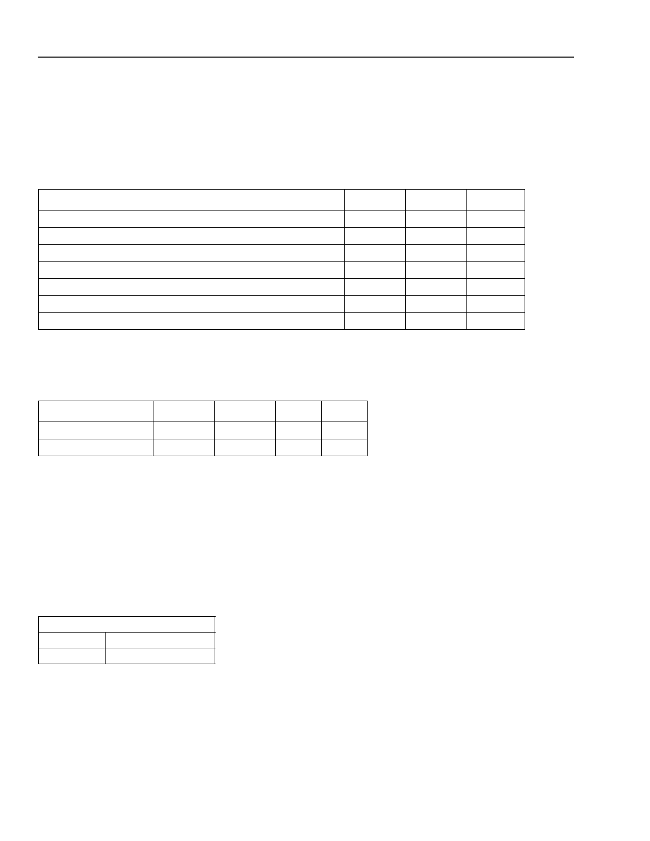
Table 2. Absolute Maximum Ratings
Parameter
Supply Voltage Range (VSS)
Power Dissipation
Voltage (all pins)
V+REF – V+IN
V–REF – V–IN
Storage Temperature Range
Operating Case Temperature Range
Min
Max
Unit
–7
0.5
V
—
1
W
VSS
0.5
V
—
±2
V
—
±2
V
–40
125
°C
0
100
°C
Recommended Operating Conditions
Table 3. Recommended Operating Conditions
Parameter
Case Temperature
Power Supply
Symbol
tCASE
VSS
Min
0
–5.7
Max Unit
70
°C
–4.7
V
Handling Precautions
Although protection circuitry has been designed into this device, proper precautions should be taken to avoid expo-
sure to electrostatic discharge (ESD) during handling and mounting. Lucent employs a human-body model (HBM)
and a charged-device model (CDM) for ESD-susceptibility testing and protection design evaluation. No industry-
wide standard has been adopted for the CDM. However, a standard HBM (resistance = 1500 Ω, capacitance =
100 pF) is widely used and, therefore, can be used for comparison purposes. The HBM ESD threshold presented
here was obtained by using these circuit parameters.
Table 4. ESD Threshold
HBM ESD Threshold
Device
Voltage
LG1605DXB
≥200 V
Mounting and Connections
Certain precautions must be taken when using solder. For installation using a constant temperature solder, temper-
atures of under 300 °C may be employed for periods of time up to 5 s, maximum. For installation with a soldering
iron (battery operated or nonswitching only), the soldering tip temperature should not be greater than 300 °C and
the soldering time for each lead must not exceed 5 s. This device is supplied with solder on the back of the pack-
age. Due to the high gain of the device, it is recommended to solder the back of the package to ground.
4
Lucent Technologies Inc.
Share Link: 