ELM337 Ver la hoja de datos (PDF) - Elm Electronics
Número de pieza
componentes Descripción
Fabricante
ELM337 Datasheet PDF : 4 Pages
| |||
ELM337
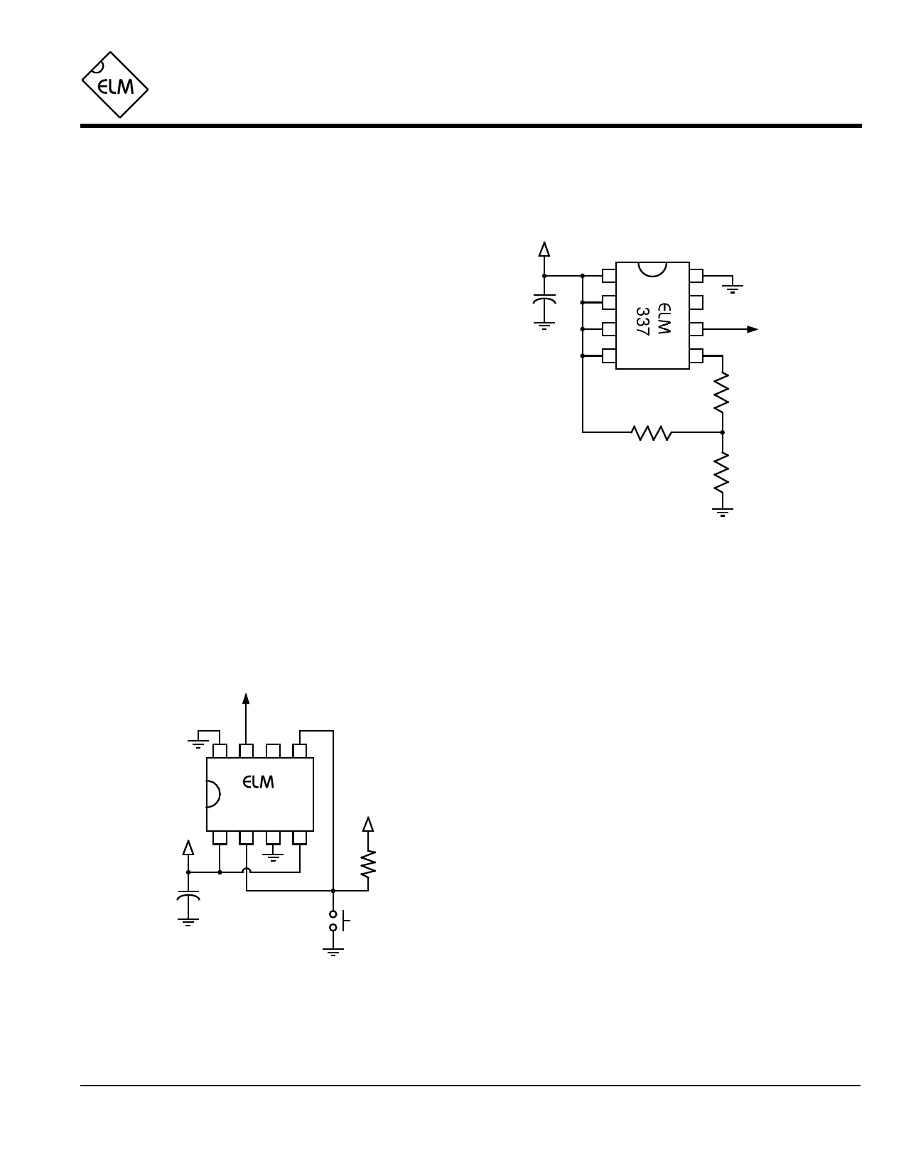
Example Applications
Figure 1 at right shows the ELM337 installed in a
typical lighting control circuit. The mode has been set to
111 (or HHH), resulting in delays of 10 minutes when
recognizing a light or dark condition. In this case, only
the ‘Dark’ output (pin 6) is used to enable (and disable) a
lighting circuit, but other variations on this theme might
use the Light output (pin 7), or possibly use mode 110 to
provide short (50 msec) output pulses to trigger other
circuits.
The threshold setting resistor (22kΩ in Figure 1) is
chosen depending on what resistance it is desired to
have the transitions to light or dark occur at. Using the
typical Schmitt voltage thresholds for a 5 volt supply, it
can be shown that the two resistances that switching will
occur at are 1.33RT (light to dark) and 0.37RT (dark to
light), where RT is the threshold setting resistance. For
the 22kΩ shown, these would be at about 30kΩ and
8kΩ, respectively. The values that you choose would
depend on the LDR used, and your application.
If the LDR (Rλ) is mounted more than a few feet
from the ELM337, the increased exposure could cause
problems due to induced voltages and currents. To
provide protection from these, a resistor (Rprot) should be
added in series with pin 5 as shown at right. Typically
this resistor would be equal in value to the threshold
setting resistor.
To the
controlled
circuit
8765
337
+5V 1 2 3 4
0.01µF
+5V
22KΩ
start
Figure 2. Time Delay Dropout Switch
+5V
0.01µF
1
8
2
7
3
6
4
5
RT
22KΩ
To the
lighting
circuit
Rprot
(see text)
Rλ
Figure 1. Yard Lighting Controller
The ELM337 is also capable of operating simply as
a delay circuit. By hard-wiring the mode pins for a
desired delay, and applying logic levels to the LDR pin,
symmetrical output delays of up to 10 minutes can be
obtained.
Asymmetrical delays can also be obtained as shown
in Figure 2. This circuit connects the ELM337 to provide
a 50msec delay on pickup and 10 second time delay on
dropout function.
Operation of the circuit can best be explained as
follows. When the ‘start’ pushbutton is pressed, the M2
and M1 pins will both be at a logic low level, while M0 will
be high. The LDR input is also at a low level, simulating
an LDR that is just ‘seeing’ light. Since the mode is 001
or LLH, then from Table 1 (on page 2) the Light output
will go to a high level after 50msec. This delay is
desirable as it ensures that the input is legitimate by
providing some degree of switch debouncing.
As soon as the pushbutton is released, the M2
mode pin returns to a high level, and what appears to be
a dark input will be on the LDR pin. From Table 1, with
mode 101, the output will turn off after 10 seconds.
Certainly several other variations are possible by
connecting the mode pins in different combinations. Why
not try your hand at some…
ELM337DSA
Elm Electronics – Circuits for the Hobbyist
< http://www.elmelectronics.com/ >
4 of 4
Share Link: 