AQC1A2-T24VDC(2013) Ver la hoja de datos (PDF) - Panasonic Corporation
Número de pieza
componentes Descripción
Fabricante
AQC1A2-T24VDC Datasheet PDF : 5 Pages
| |||
ACCESSORY
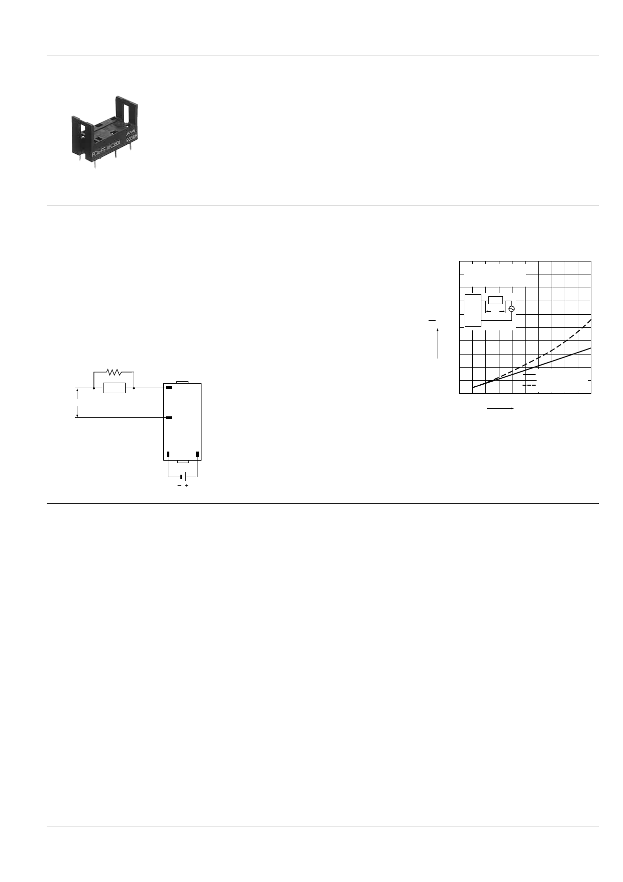
Socket
AQ-C
PC1A-PS
NOTES
When used for the load less than rated
In the case of the load current less than
rated, malfunction may result from the
residual voltage across the both ends of
the load even if the solid state relay is
turned off.
Use a dummy resistor as a
countermeasure.
The total of the current through the
resistor and the load current must exceed
the min. rated load current.
R0 (Dummy resistor)
In case the dummy resistor is not used,
keep in mind that the residual voltage
becomes as follows:
Example:
For the inductive load by the 5 mA load
current and the 200 V AC load voltage,
the load impedance becomes 40 kΩ and
Ve/V = 16% is estimated from the below
graph.
Accordingly, the 32 V voltage remains
across the both ends of the load when
the solid state relay is turned off.
(+)
Load
8
Load power source
(–)
5
• Characteristics of residual voltage
vs. load impedance (AC output)
100
f = 60 Hz
Ve: Residual voltage
V: Power voltage
80
1 Load
Ve
V
60
×100,%
SSR
2
Ve
V
40
20
Power factor: 1
(resistive load)
Power factor: 0.4
(inductive load)
0
20
40
60
80
100
Load impedance, kΩ
1 16
Input power source
Panasonic Corporation Automation Controls Buisiness Division
industrial.panasonic.com/ac/e/
–5–
© Panasonic Corporation 2013
ASCTB214E 201312-T
Share Link: 