HLG-600H Ver la hoja de datos (PDF) - Unspecified
Número de pieza
componentes Descripción
Fabricante
HLG-600H Datasheet PDF : 8 Pages
| |||
H L G - 6 0 0 H 600W Constant Voltage + Constant Current LED Driver
series
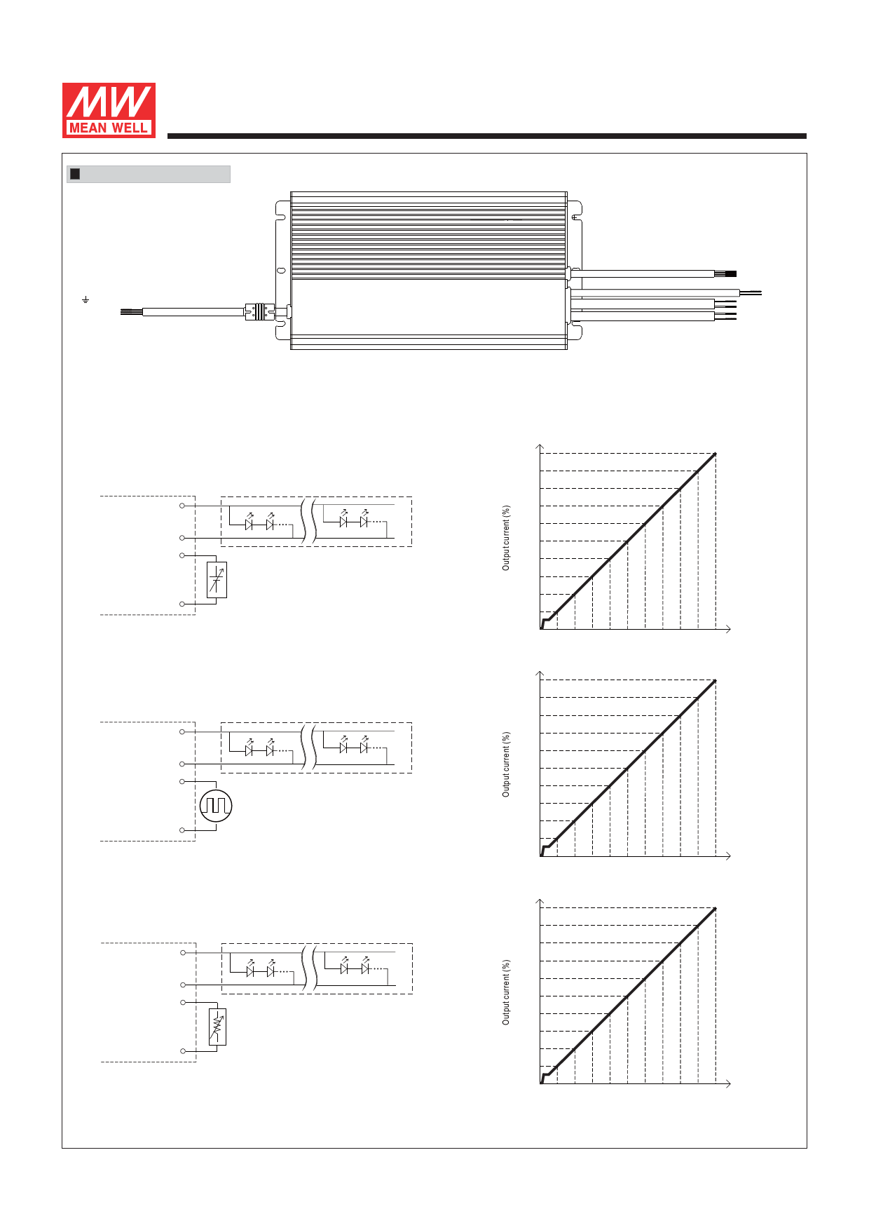
DIMMING OPERATION
FG (Green/Yellow)
AC/L(Brown)
AC/N(Blue)
HLG-600H
RC+(Brown)
RC- & GND(Black)
+5VSB(Yellow)
DIM+(Blue)
DIM-(White)
-V(Black)
+V(Red)
-V(Black)
+V(Red)
※ 3 in 1 dimming function (for B-Type)
Output constant current level can be adjusted by applying one of the three methodologies between DIM+ and DIM-:
0 ~ 10VDC, or 10V PWM signal or resistance.
Direct connecting to LEDs is suggested. It is not suitable to be used with additional drivers.
Dimming source current from power supply: 100μA (typ.)
◎ Applying additive 0 ~ 10VDC
100%
90%
+V +
80%
+
70%
-
-V
60%
-
50%
DIM+
40%
+
Additive Voltage
30%
-
20%
DIM-
10%
“DO NOT connect "DIM- to -V"
0%
0V 1V 2V 3V 4V 5V 6V 7V 8V 9V 10V
Dimming input: Additive voltage
◎ Applying additive 10V PWM signal (frequency range 100Hz ~ 3KHz):
+V +
+
-
-V
-
DIM+
Additive PWM signal
DIM-
“DO NOT connect "DIM- to -V"
100%
90%
80%
70%
60%
50%
40%
30%
20%
10%
0%
0% 10% 20% 30% 40% 50% 60% 70% 80% 90% 100%
Duty cycle of additive 10V PWM signal dimming input
◎ Applying additive resistance:
100%
90%
+V +
80%
+
70%
-
-V
DIM+
60%
-
50%
40%
Additive Resistance
30%
DIM-
20%
10%
“DO NOT connect "DIM- to -V"
0%
Short 10K/N 20K/N 30K/N 40K/N 50K/N 60K/N 70K/N 80K/N 90K/N 100K/N
(N=driver quantity for synchronized dimming operation)
Note : 1. Min. dimming level is about 6% and the output current is not defined when 0%< Iout<6%.
Dimming input: Additive resistance
2. The output current could drop down to 0% when dimming input is about 0kΩ or 0Vdc, or 10V PWM signal with 0% duty cycle.
File Name:HLG-600H-SPEC 2016-10-27
Share Link: 