FW1201S31 Ver la hoja de datos (PDF) - TE Connectivity
Número de pieza
componentes Descripción
Fabricante
FW1201S31 Datasheet PDF : 3 Pages
| |||
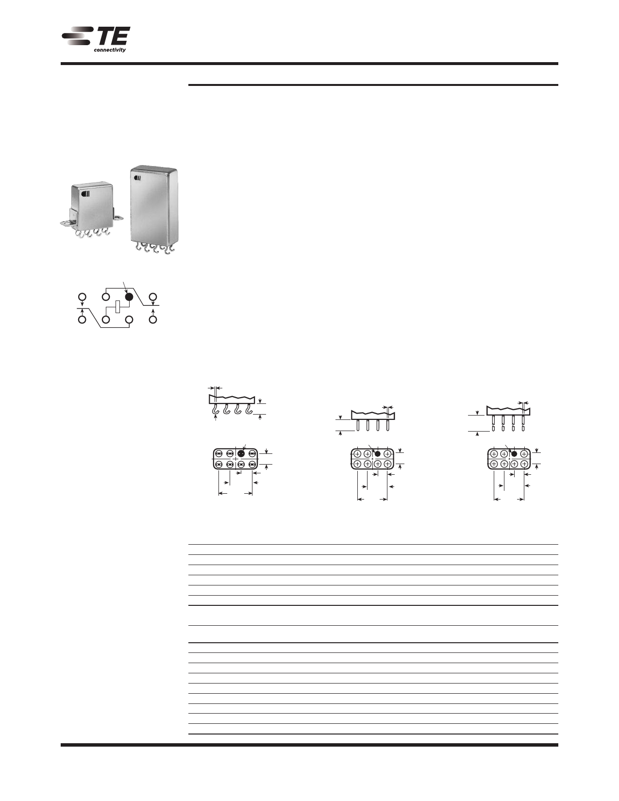
CII Low Signal Relays
Double Pole, Electrically Held, 5 Amps and Less (Continued)
FW, FW5A, SF, SF5A
Two Pole Full Size
Crystal-Can Relay
FW Qualified to
MIL-R-5757/10
FW
B1
A2
SF
BLUE BEAD
X1
A3
(+)
B3
X2
B2
A1
Terminal View
Product Facts
n Hermetically sealed
n Up to 5 amps switching
n High shock & vibration
ratings
n Optional terminals &
mounting options
n Excellent RF switching
Electrical Characteristics
Contact Arrangement —
2 Form C
Contact Material —
Stationary —
Bifurcated hardened silver alloy
Moveable —
Gold plated hardened alloy
Contact Resistance —
Before Life — 50 milliohms max.
(measured at 10 mA @ 6 Vdc)
After Life — 100 milliohms max.
(measured @ 2 mA @ 28 Vdc)
Mechanical Life Expectancy —
50 million operations
Coil Voltage —
6.3 to 110 Vdc (FW, FWSA)
1.8 to 40 Vdc (SF)
2.8 to 40 Vdc (SFSA)
Coil Power — 1.5 watts max. @ 25°C
Duty Cycle — Continuous
Pick-up Voltage — Approximately
50% of nominal coil voltage
Pick-up Sensitivity —
250 mW (FW, FWSA)
40 mW (SF)
80 mW (SF5A)
1
.030 +.003 –.002
(0.76 +.08 –.06)
.030 RAD.
(.76)
.210
(5.33) MAX
CL BLUE BEAD
CL
.400
(10.16)
.600
(15.24)
.200
(5.08)
Operating Characteristics
Operate Time —
15 ms max. (SF)
5 ms (FW, FWSA))
6 ms max. (MIL-R-5757/10)
Release Time —
10 ms max. (SF)
5 ms max. (FW, FWSA)
6 ms max. (MIL-R-5757/10)
Contact Bounce — 2 ms max.
Dielectric Withstanding Voltage —
Between Open Contacts —
500 Vrms 60 Hz
Between Adjacent Contacts —
1,000 Vrms 60 Hz
Between Contacts and Coil —
1,000 Vrms 60 Hz
Insulation Resistance —
10,000 megohms min @ 500 Vdc
Environmental Characteristics
Temperature Range —
-65°C to +125°C
Weight —
0.6 oz. max. (FW, FWSA)
0.7 oz. max. (SF 6)
1.1 oz. max. (SF/SF 5A)
Vibration Resistance —
Standard —
20 G’s, 10 to 2000 Hz (FW, FWSA)
15 G’s, 10 to 2000 Hz (SF)
QPL —
20 G’s, 10 to 2000 Hz
Shock Resistance —
100 G’s, 6 ±1 ms
QPL Approval —
MIL-R-5757/10 (FW only)
QPL Equivalent —
MIL-R-5757/13 (SF only)
2
.187±.020
(4.75 ±.51)
.030 +.003 –.002
(0.76 +.08 –.06)
BLUE
.400
(10.16)
.600
(15.24)
.200
(5.08)
3
3.000 ±.000
(76.20 ±.76)
BLUE
.030 +.003 –.002
(0.76 +.08 –.06)
.400
(10.16)
.600
(15.24)
.200
(5.08)
1–68
Catalog 5-1773450-5
Revised 3-13
www.te.com
RF Performance
Frequency (MHz)
100
250
500
750
1,000
Terminals
RF Losses (dB)
0.1
0.2
0.3
0.4
0.4
VSWR
1.17:1
1.18:1
1.19:1
1.19:1
1.19:1
Contact Ratings
Contact
Load
5 A @ 28 Vdc (FW5A/SF5A)
3 A @ 28 Vdc (FW)
2 A @ 28 Vdc (SF)
1 A @ 115 Vac, 60 Hz & 400 Hz (FW)
0.3 A @ 115 Vac, 60 Hz & 400 Hz (SF)
1 A @ 28 Vdc
0.1 A @ 28 Vdc
10 µA @ 50 mVdc
75 WATTS @ 50 MHz (FW)
Type
Resistive
Resistive
Resistive
Resistive
Resistive
Inductive (200 mH)
Lamp
Low Level
RF
Isolation (dB)
40
33
28
25
23
Operations
Min.
100,000
100,000
100,000
100,000
100,000
100,000
100,000
1,000,000
10,000,000
Dimensions are shown for
reference purposes only.
Specifications subject
to change.
Dimensions are in millimeters USA: +1 800 522 6752
unless otherwise specified. Asia Pacific: +86 0 400 820 6015
UK: +44 800 267 666
For additional support numbers
please visit www.te.com
Share Link: 